Dismantling
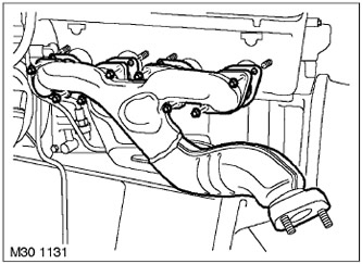
1. Turn away 8 nuts of fastening of a final collector, remove a collector, utilize nuts and both linings.
2. Disconnect the cooling system hoses from the fluid pump.
V8 engine, ENGINE OVERHAUL, Hoses connecting distributor pipe to coolant pump.
3. Remove the left camshaft adjuster.
V8 Engine, ENGINE OVERHAUL, Variable Valve Timing (VCC).
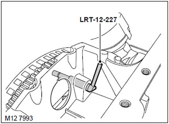
4. Remove the LRT-12-227 pin from the retainer hole.
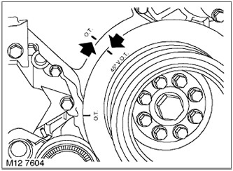
5. Turn the crankshaft counterclockwise to the 45°position to T.M.T.
NOTE: Tighten the camshaft timing chain while turning the crankshaft and keep it taut.
6. Remove the LRT-12-223/6, LRT-12-223/5, LRT-12-223/3 and LRT-12-223/4 tools from the left cylinder head camshafts.
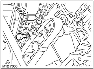
7. Turn away a bolt of fastening of a shoe of a chain to the left head of cylinders.
Disassembly
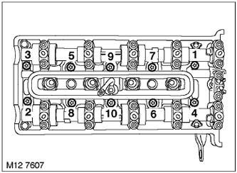
1. Loosen the 10 cylinder head bolts in the sequence shown in the figure.
2. Discard head bolts and remove 10 bolt washers.
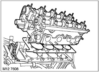
3. With the help of a partner, remove the cylinder head.
4. Dispose of the cylinder head gasket.
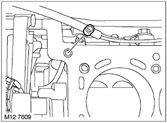
5. Dispose of the O-ring on the top plane of the cylinder block.
Examination
1. Clean the surfaces of the block head, cylinder block, pins and pin holes. If necessary, remove residual sealant with a hardwood scraper. Make sure that no residue of the removed sealant gets into the oil and water channels and threaded sockets.
CAUTION: Make sure that no oil or coolant remains in the threaded sockets of the cylinder block. If this is not done, then, when tightening the head bolts, the cylinder block can be damaged.
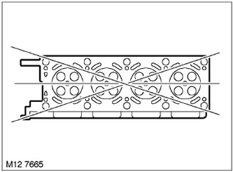
2. Using a straightedge and a feeler gauge, check the deformation of the bottom plane of the head in the directions shown in the figure.
TECHNICAL DATA, Engine - V8.
Assembly
1. Fit a new O-ring to the cylinder block.
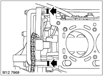
2. Apply STC 50550 sealant to the places indicated in the figure.
3. Slide a new head gasket over the dowel pins in the cylinder block.
4. With the help of a partner, place the head on the block, making sure that it hits the pins.
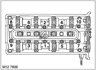
5. Replace the head bolt washers and install new bolts. Tighten the head mounting bolts to 30 Nm in the sequence shown in the figure. Using an angle torque wrench, in the same sequence, tighten the bolts by 80°, and then another 80°.
NOTE: Do not attempt to remove the coating from new bolts.
Assembly
1. Screw in the left camshaft drive chain shoe mounting bolt and tighten it to 10 Nm.
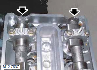
2. Carefully rotate the camshafts until the cylinder letters and numbers located at the rear of the shafts point upwards.
3. Loosen the bolt securing the mandrel LRT-12-223/4 to the mandrel LRT-12-223/3.
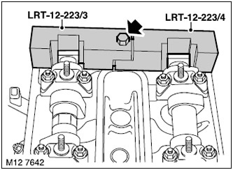
4. Install mandrels LRT-12-223/4 and LRT-12-223/3 on the rear of the camshafts of the left cylinder head and tighten the bolt.
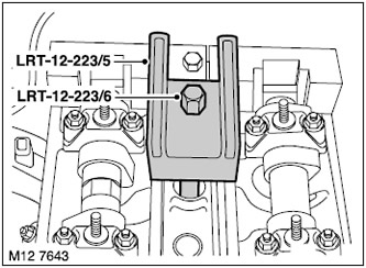
5. Fit mandrels LRT-12-223/5 and LRT-12-223/6 to the left cylinder head and tighten LRT-12-223/6 using the threaded spark plug socket.
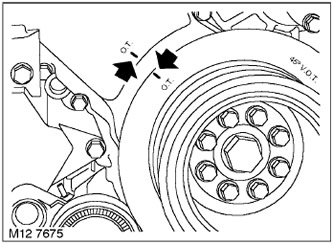
6. Turn the crankshaft clockwise until the V.M.T.
NOTE: Tighten the camshaft timing chain while turning the crankshaft and keep it taut.
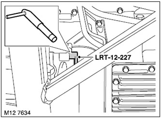
7. Insert pin LRT-12-227 through hatch and lock flywheel in T.D.T.
8. Install the left camshaft adjuster.
V8 Engine, ENGINE OVERHAUL, Variable Valve Timing (VCC).
9. Attach hoses of system of cooling to the liquid pump.
V8 engine, ENGINE OVERHAUL, Hoses connecting distributor pipe to coolant pump.
10. Wipe the mating surface of the exhaust manifold and install new gaskets.
11. Apply grease with copper powder to the exhaust manifold mounting studs, screw on the 8 manifold mounting nuts and tighten them to 23 Nm.
Comments on this article