Removing
1. Place the car on a lift.
2. Disconnect "negative" battery wire.
3. Raise the vehicle.
4. Remove the exhaust system.
EXHAUST MANIFOLD AND EXHAUST GAS SYSTEM: Td6 engine, REPAIR WORK, Exhaust system and suspension of system elements.
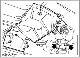
5. Turn away 8 nuts of fastening of the average heat-insulating screen and remove the screen.
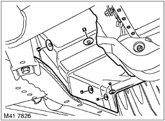
6. Turn away 5 nuts, release and remove the right heat-insulating screen.
7. Install a hydraulic support stand under the gearbox.
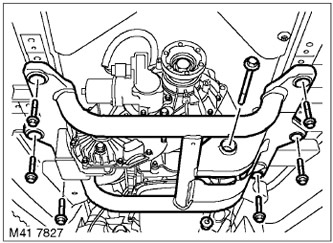
8. Turn away a nut and a bolt of fastening of a support to a cross beam.
9. Turn away 6 bolts of fastening of a crossbeam and remove it.
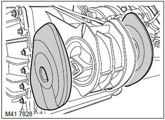
10. Remove shock-absorbing pillows from a support.
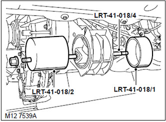
11. Lubricate the middle screw of tool LRT-41-018/4 with molybdenum disulphide grease and assemble the tool to remove the support from the transfer case, as shown in the figure.
CAUTION: Make sure the tool position indicator is set to 6 o'clock. The position indicator is a milled flat on the components LRT-41-018/1 and LRT-41-018/2 fixtures.
Installation
1. Wipe the mating surfaces.
2. Lubricate the new support and drill in the transfer case to facilitate assembly.
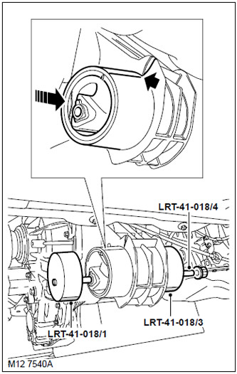
3. Install the new support against the rear of the transfer case and begin to slide it into place. The support must be parallel to the surface of the transfer case with match marks aligned.
NOTE: To facilitate installation, duplicate the alignment marks on the side of the support.
4. Lubricate the center screw of tool LRT-41-018/4 with molybdenum disulphide grease and assemble the transfer case support tool as shown. Start the installation with the middle screw completely turned out, when the support is installed at about 75%, the screw must be fully screwed into the LRT-41-018/1 faceplate in order to reduce its length. This is necessary so that the middle screw of the LRT-41-018 / 4 device does not touch the gearbox pan.
CAUTION: Make sure the tool position indicator is set to 6 o'clock.
5. Ensure proper support installation (parallel to the surface of the transfer box). If necessary, correct the position of the support using a mallet.
6. Install cushion pads.
7. Install the cross beam on the support, install the bolt and nut, but do not tighten it.
8. Install the cross beam in place, screw in the bolts and tighten them. Tightening torque 90 Nm.
9. Remove the hydraulic strut from under the gearbox.
10. Tighten the nut and bolt securing the support to the cross beam. Tightening torque 74 Nm.
11. Install heat shield and secure with nuts.
12. Install the middle heat shield and secure with nuts.
13. Install the exhaust system.
EXHAUST MANIFOLD AND EXHAUST GAS SYSTEM: Td6 engine, REPAIR WORK, Exhaust system and suspension of system elements.
14. Attach "negative" wire to the battery.
Comments on this article