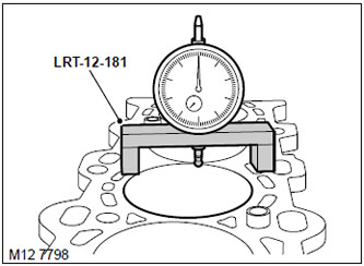
1. The top plane of the block of cylinders and the bottom of pistons should be pure.
2. Fix the dial indicator in the LRT-12-181 rack and install it on the cylinder block.
3. Expose "zero" indicator.
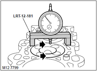
4. Place an indicator on the piston crown and measure the piston protrusion at two points as shown. By rotating the crankshaft, set the piston to the position corresponding to T.M.T. Record all measured piston protrusions and repeat the procedure for all pistons.
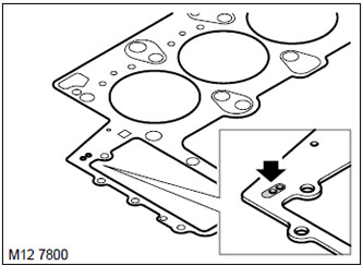
5. The largest piston protrusion determines the required thickness of the cylinder head gasket.
6. If the protrusion of the piston is from 0.92 to 1.03 mm, then a gasket with two notches must be installed.
7. If the protrusion of the piston exceeds 1.03 mm, then a gasket with three notches must be installed.
Checking the protrusion of the pistons with the cylinder head removed (Range Rover 3)
This article is available at russian, bulgarian, belarusian, ukrainian, serbian, croatian, romanian, polish, slovak, hungarian
Previous articles
Valve timing — check and adjustment
Oil pressure check
Intake and exhaust camshafts
Crankshaft pulley
Replacing the front crankshaft oil seal
Replacement of a back epiploon of a cranked shaft
Cylinder head gasket
Hydraulic expansion joints
Valve cover gasket
Soundproof engine cover
Upper engine cover
Removal and installation of the engine
Electrovacuum valve control system
Rear engine mount
Left engine mount
Right engine mount
Converter Drive Drive
Oil filter head gasket
Oil filter
Oil pickup tube with strainer
Oil pump
Engine pan gasket
Oil pressure switch
Laying of the engine oil cooling heat exchanger
Gear cover of the gas distribution mechanism
Gas distribution gear cover gasket
Piston group
Replacing connecting rod bearings
Current article
Checking the protrusion of the pistons with the cylinder head removed
Next articles
Similar articles from Land Rover repair manuals:
• Checking the protrusion of the pistons with the cylinder head removed Freelander 1 (1997-2006)
• Elements of the cylinder head Freelander 2 (2006-2014)
• Cylinder head parts Discovery 3 (2004-2009)
• Cylinder head — removal and installation Defender 2007+ (2007-2016)
• Checking the protrusion of the pistons with the cylinder head removed Freelander 1 (1997-2006)
• Elements of the cylinder head Freelander 2 (2006-2014)
• Cylinder head parts Discovery 3 (2004-2009)
• Cylinder head — removal and installation Defender 2007+ (2007-2016)
No comments yet
Comments on this article