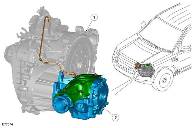
NOTE: Manual transmission shown, automatic transmission similar.
| Pos. | spare part no | Name |
| 1 | - | Transmission |
| 2 | - | Transfer case |
The transfer case is located at the rear of the engine and is fixed directly to the gearbox housing and cylinder block using a bracket. The petrol and diesel versions, manual and automatic transmissions use the same transfer case.

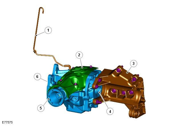
| Pos. | spare part no | Name |
| 1 | - | Breather pipeline |
| 2 | - | heat shield |
| 3 | - | Engine support bracket |
| 4 | - | Consolidation of the right semiaxis |
| 5 | - | propshaft support flange |
| 6 | - | Gearbox differential input shaft splines |
The transfer case is driven directly from the gearbox differential by means of a hollow shaft through which the right axle shaft passes. (The left axle shaft is driven directly from the gearbox differential). Drive power is transmitted to the driveshaft via a low-offset hypoid bevel gear set that is configured to minimize power loss throughout the speed range. The transfer case transfers torque from the transmission differential to the driveshaft and rear differential. The torque from the transfer case is not transmitted to the front axle shafts.
Transfer case features:
- Torque 1500 Nm.
- Output gear ratio to cardan shaft 2.58:1.
- Filled with oil for life.
- Separate breather.
The transfer case is equipped with an internal bearing preload system. This allows the seal to be changed during maintenance without disturbing the bearing preload.
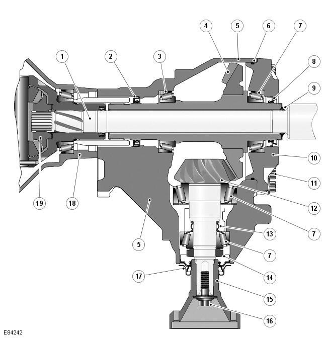
Transfer box in section

| Pos. | spare part no | Name |
| 1 | - | Right half shaft |
| 2 | - | Oil seal |
| 3 | - | Tapered roller bearing |
| 4 | - | ring gear |
| 5 | - | Lid |
| 6 | - | Sealing ring |
| 7 | - | Tapered roller bearings |
| 8 | - | Oil seal and flinger ring |
| 9 | - | Oil seal |
| 10 | - | Carter |
| 11 | - | bolts |
| 12 | - | pinion gear |
| 13 | - | Deformable spacer |
| 14 | - | Preload Nut |
| 15 | - | drive flange |
| 16 | - | Shoulder bolt |
| 17 | - | Oil seal and flinger ring |
| 18 | - | gearbox housing |
| 19 | - | Gearbox differential |
The transfer case includes a ring gear and a drive shaft-pinion, which are located in the cover.
The crown gear is installed longitudinally in the transfer case. The left end of the gear has splines that mate with the corresponding splines in the output hub of the transmission differential. The gear is hollow, which allows you to install the right half shaft. The axle shaft passes through the hollow gear and engages with the splines of the gearbox differential. The axle shaft is driven by the gearbox differential and does not receive torque from the transfer case.
The ring gear is supported in the cover by opposing tapered roller bearings which are pressed into the cover and crankcase. The gear is held in the cover by the crankcase, which is bolted to the cover and sealed with an O-ring. At the outer end of the crankcase, a triangular oil seal and an oil flinger are installed to prevent dirt and moisture from entering the gear. Another seal prevents the penetration of dirt and moisture between the gear and the right axle shaft.
The drive gear is located in the crankcase at an angle of 90 degrees with respect to the ring gear. The drive pinion is supported in the cover by opposing tapered roller bearings. The drive gear is held in the crankcase by a preload nut. The outer end of the pinion gear is splined and engages with the driveshaft output flange. The flange is secured with a shoulder bolt that is screwed into the pinion gear.
The deformable spacer is located between the outer tapered roller bearing and the boss on the drive gear. The deformable spacer maintains bearing adjustment and also deforms under pressure applied to the preload nut. This allows the nut to be tightened to the specified torque, deforming the spacer, which establishes the correct bearing preload and correct pinion and ring gear engagement.
The transmission differential drives the ring gear, which in turn drives the pinion gear. The drive gear drives the driveshaft and rear differential through a drive flange attached to the drive gear shaft.
Comments on this article