Special tool
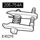 205-754A Splitter, Ball Joints 205-754A Splitter, Ball Joints | 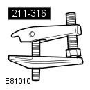 211-316 Separator, Ball Joint 211-316 Separator, Ball Joint |
General Equipment: Powertrain Jack
NOTE: If it is necessary to remove the transmission, it is not necessary to drain the transmission fluid unless the fluid cooler is disconnected from the transmission assembly.
NOTE: If the transmission is removed for access, the transmission fluid does not need to be drained because the transmission fluid cooler is not detached from the transmission assembly.
1. Remove the battery tray. Refer to procedure: Battery installation shelf (414-01 Battery, battery mount and wires, Removal and installation).
2. Raise and support the vehicle.
WARNING: Place secure stands under the vehicle.
3. Pump out a liquid from a tank of the amplifier of a steering.
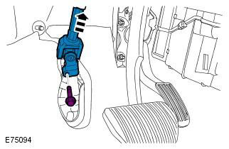
4. Disconnect the bottom section of a steering column from the steering mechanism.
WARNING: Install a new steering column flexible coupling bolt.
5. Remove the starter. Refer to procedure: Starter (303-06B Starting system - 2.2L Duratorq - Td4, Removal and installation).
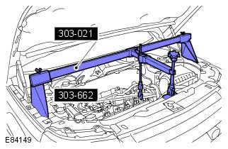
6. Support the engine.
7. Remove the bracket.
WARNING: Use new nuts.
NOTE: Vehicles with automatic transmission have the breather line attached to the support.
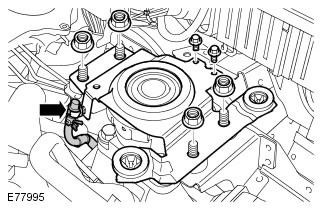
8. Remove the left engine mount.
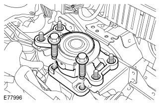
9. Remove the ground strap.
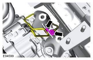
10. Remove the engine support bracket.
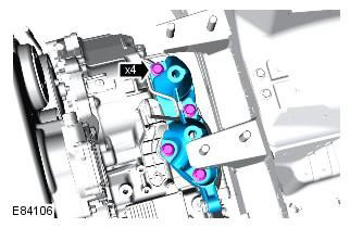
11. Release and disconnect a cable of the selector lever.
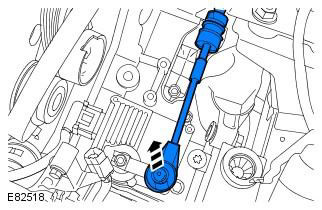
12. Drain the gearbox oil. Refer to Procedure: Draining and Refilling Transmission Fluid - 2.2L Duratorq - Td4 (307-01 Automatic Transmission/Transaxle Transmission, General Procedures).
13. Remove the front wheels with tires. Refer to procedure: Wheel and tire (204-04 Wheels and tires, Removal and installation).
14. Remove the towing device hole plug.
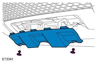
15. Remove the 2 bolts securing the bumper cover.
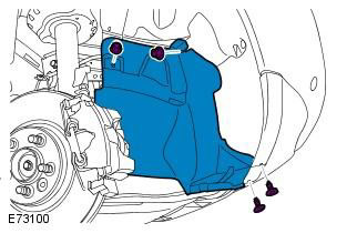
16. Remove both wing mudguard extension panels.
NOTE: The illustration shows the right side, on the left side the procedure is the same.
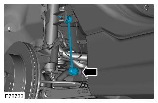
17. Disconnect both forward racks from the stabilizer.
CAUTION: Do not allow the ball joint to rotate.
NOTE: Discard 2 nuts.
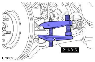
18. Using the special tool, disconnect the ball joints of the left and right tie rod ends. Special tool: 211-316
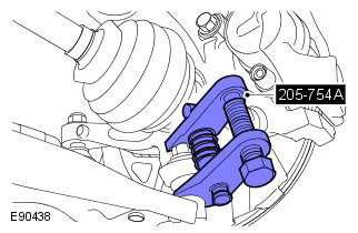
19. Using the special tool, remove the lower arm ball joint. Special tool: 205-754A
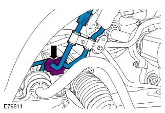
20. Disconnect the PAS lines.
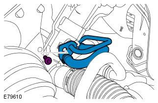
21. Disconnect pressure hoses from the hydraulic booster mechanism.
CAUTION: Fluid may leak.
NOTE: Plug all openings.
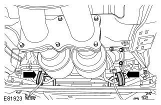
22. Disconnect catalytic converter with a distributive pipe.
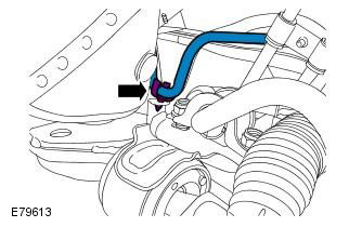
23. Disconnect the fuel line.
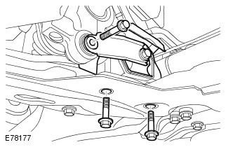
24. Remove the bottom support pad.
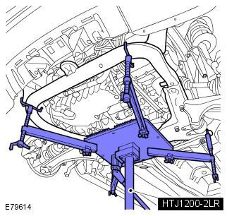
25. Support the subframe. General Equipment: Powertrain Jack
26. Remove the cross member of the front subframe.
CAUTION: Use only new subframe bolts.
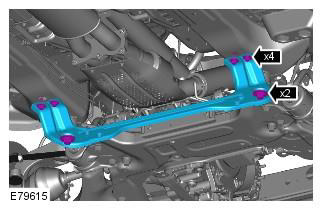
27. Lower the front subframe assembly.
Mark the position of the elements to facilitate subsequent installation. Use only new subframe bolts.
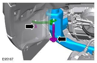
28. Remove the exhaust pipe from the turbocharger.
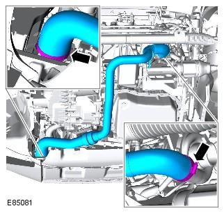
29. Disconnect the two transmission heat exchanger lines.
Prepare to collect spilled liquid. Plug all openings. Discard seals. Clean the area around the element and remove foreign matter from it.
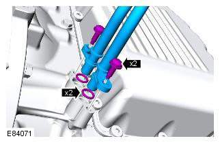
30. Disconnect the left axle shaft.
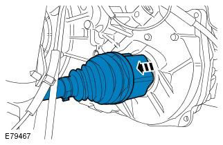
31. Disconnect the right half shaft.
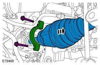
32. Remove the access cover.
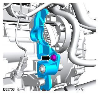
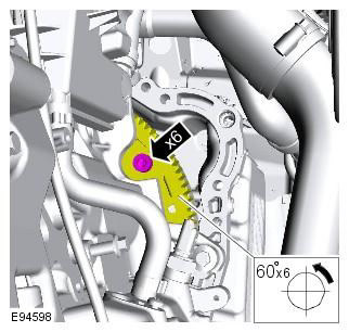
33. Remove and reject the torque converter mounting bolts.
NOTE: Discard bolts.
34. Support the gearbox. General Equipment: Powertrain Jack
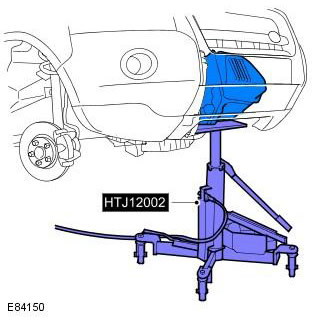
35. Remove a transmission and the hydrotransformer.
CAUTION: Make sure the torque converter remains in the transmission.
NOTE: This step requires the assistance of a second mechanic.
36. Install the torque converter holder.
CAUTION: Make sure the pins are on the engine and not on the gearbox.
Comments on this article