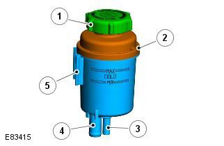
| Pos. | spare part no | Name |
| 1 | - | Lid |
| 2 | -Frame | |
| 3 | - | Return connection (DW12 - from the steering gear) (i6 - from the working fluid cooler) |
| 4 | - | suction connection (from the power steering pump) |
| 5 | - | Bracket Mounts |
The fluid reservoir is located on a bracket on the right side of the engine compartment behind the headlight assembly. The tank consists of a body, a lid and a filter. The purpose of the tank is to provide additional supply of the working fluid to the system in case of its thermal expansion or contraction.
Maintaining the fluid in the tank at the required level allows you to ensure that the supply hose at the bottom of the tank is filled with liquid in any position of the car. If air is present in the system, it exits it into the tank.
The housing is molded from plastic and has two branch pipes at the bottom for fastening the supply and return hoses. The marking on the wall serves to indicate the maximum and minimum levels. A non-replaceable nylon mesh filter 100 microns thick is installed in the tank body. The filter prevents solids from the reservoir from entering the pump. The maximum and minimum fluid levels are marked on the housing to help you check the fluid level when cold.
To remove the cap from the neck of the tank, the cap must be turned counterclockwise. The reservoir cap is equipped with an O-ring to prevent leakage and has a breather that allows the fluid in the reservoir to change its level during movement without creating a vacuum or overpressure.
Comments on this article