Special tool
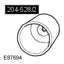 204-528/2 Remover/Installer, Bushing 204-528/2 Remover/Installer, Bushing | 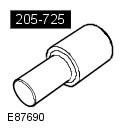 205-725 Remover/Installer, Wheel Hub 205-725 Remover/Installer, Wheel Hub | 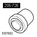 205-726 Remover/Installer, Wheel Hub Bearing 205-726 Remover/Installer, Wheel Hub Bearing |
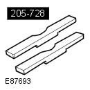 205-728 Remover/Installer, Wheel Hub 205-728 Remover/Installer, Wheel Hub | 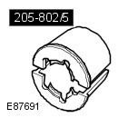 205-802/5 Remover, Wheel Hub/Bearing 205-802/5 Remover, Wheel Hub/Bearing |
Removing
1. Raise the vehicle.
WARNING: Place secure stands under the vehicle.
2. Remove the wheel. Refer to procedure: Wheel and tire (204-04 Wheels and tires, Removal and installation).
3. Remove a rotary fist. Refer to Procedure: Wheel Knuckle (204-02 Rear suspension, Removal and installation).
4.
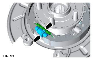
5.
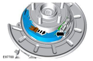
6.
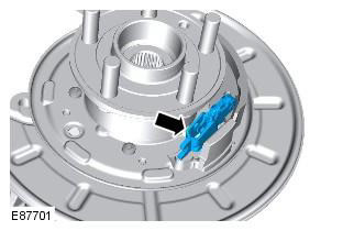
7.
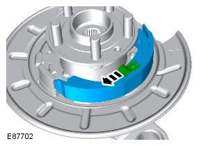
8.
- Install the steering knuckle assembly in a vise so that it rests on the special tool. Special tool (s): 205-802/5
- Press the drive flange out of the steering knuckle using the special tool. Special tool (s): 205-725
NOTE: Bearing damage is inevitable during this operation.
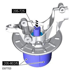
9.
NOTE: The inner race of the bearing will remain on the drive flange.
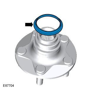
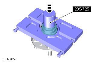
10.
- Squeeze the halves of a suitable bearing cage around the inner race of the bearing and place the drive flange in a vise.
- Using the special tool, press the drive flange out of the inner race of the bearing. Special tool (s): 205-725
11. Remove a lock ring from a rotary fist in gathering.
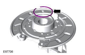
12.
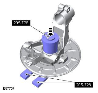
- Install the steering knuckle assembly in a vise so that it rests on the special tool. Special tool (s): 205-728
- Using the special tool, press the wheel bearing out of the steering knuckle. Special tool (s): 205-726
Installation
1.
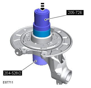
- Install the steering knuckle assembly in a vise so that it rests on the special tool. Special tool (s): 204-528/2
- Using the special tool, press the new wheel bearing into the steering knuckle. Special tool (s): 205-726
CAUTION: One side of the bearing is magnetized. The magnetized side can be recognized by the black matte finish. The magnetic side must face the inside of the vehicle. Before installing the bearing, make sure that the magnetic side is not dirty. Take special care when handling the bearing.
2. Install the circlip on the steering knuckle assembly.
3.
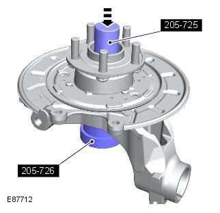
- Install the steering knuckle assembly in a vise so that it rests on the special tool. Special tool (s): 205-726
- Press the drive flange into the steering knuckle using the special tool. Special tool (s): 205-725
4. Clean the skid plate and apply grease to the surfaces in contact with the brake pads.
WARNING: Do not use compressed air to clean brake components. Dust from friction materials is harmful when it enters the lungs.
5. Clean the regulator and set the minimum length of the regulator.
6.
- Install the secondary brake pad.
- Install the spring retainer and pin.
7.
- Install the adjusting plate and spring.
- Install the primary brake pad.
- Install the return spring.
- Install the spring retainer and pin.
WARNING: Make sure the return spring and adjusting spring are properly installed on the primary shoe.
CAUTION: Do not overstretch the brake shoe spring.
8. Install the brake shoe adjuster.
CAUTION: Do not overstretch the brake shoe spring.
9. Establish a rotary fist. Refer to Procedure: Wheel Knuckle (204-02 Rear suspension, Removal and installation).
10. Adjust the parking brake. Refer to Procedure: Parking Brake Cable Adjustment (206-05 Parking Brake and Parking Brake Actuator, General Procedures).
11. Install the wheel and tire. Refer to procedure: Wheel and tire (204-04 Wheels and tires, Removal and installation).
Comments on this article