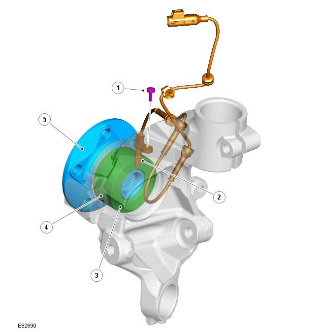
| Pos. | spare part no | Name |
| 1 | - | Screw |
| 2 | - | Wheel speed sensor |
| 3 | - | Bearing seal and magnetic impulse wheel |
| 4 | - | wheel bearing |
| 5 | - | wheel hub |
An active wheel speed sensor is mounted on the knuckle of each wheel. They provide the ABS module with a speed signal from each wheel. The head of each wheel speed sensor is located close to the magnetic impulse wheel built into the wheel bearing seal. Each impulse wheel on front axle bearings contains 44 north and south poles; each impulse wheel on the rear axle bearing has 48 pairs of poles. A jumper wire connects each sensor to the vehicle's wiring harness.
The wheel speed sensor receives its electrical power from the ABS module and is also connected to it by an electrical signal circuit. When the ignition switch is in power mode 6 (ignition), the ABS module supplies power to the wheel speed sensors and monitors the feedback. The rotation of the wheels initiates current fluctuations in the return signals of the speed sensors. The ABS module subsequently converts the feedback signals into individual wheel speeds and overall vehicle speed.
The ABS module communicates individual wheel speeds and vehicle speeds over the high speed CAN bus for use by other systems. Information about the quality of the vehicle speed signal is also broadcast over the high-speed CAN bus. If there are speed signals from all wheels to calculate the vehicle speed, the quality of the vehicle speed signal is set to "calculated data within the prescribed accuracy". If one or more wheel speed sensors are not working, the quality of the vehicle speed signal is set to "accuracy is not correct".
The ABS module monitors the wheel speed sensor circuits for faults. If a malfunction is detected, the ABS module stores the appropriate DTC in memory and the corresponding warning lamps come on, depending on the functions in question (DSC/ETC, ABS, EBA/EBD, HDC). A warning horn also sounds to warn the driver of a malfunction.
On vehicles equipped with an instrument panel "high series", the message center message is displayed only if the fault affects the operation of the HDC.
For more information, see the chapter:
- instrument panel (413-01 Instrument panel, Description and function)
- Information and message center (413-08 Information and Message Centre, Description and Operation)
Since the wheel speed sensors are active devices, there is a feedback signal when the wheels are not spinning. This gives the ABS module the ability to check the status of the speed sensors when the vehicle is stationary.
Sensor block

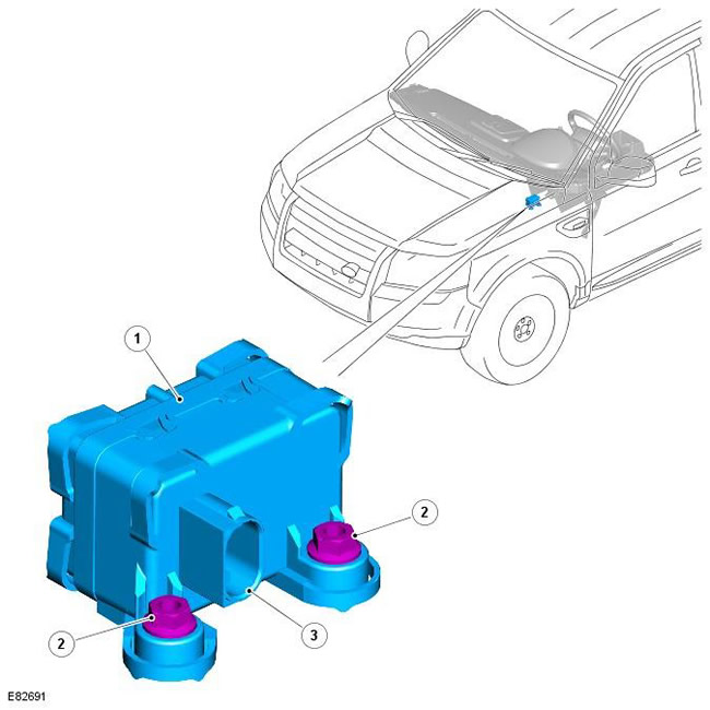
| Pos. | spare part no | Name |
| 1 | - | Sensor block |
| 2 | - | Stud and nut (2 pcs.) |
| 3 | - | electrical connector |
The sensor unit is mounted below the center console and is attached to the transmission tunnel with two studs and nuts. The sensor box is a compact unit that provides input signals to the ABS module for yaw rate, roll rate, longitudinal and lateral acceleration. The ABS module transmits input signal values via the high speed CAN bus for use by other systems.
When the ignition is in power mode 6 (ignition), the sensor block is powered by the ABS module when the ignition is on. The sensor block is also connected to the ABS module via a private CAN bus.
Sensor block diagnostics are performed by the ABS module. If a sensor malfunction is detected, the ABS module stores the appropriate DTC in memory and the appropriate warning lamps illuminate, depending on the functions being considered (DSC/ETC, ABS, EBA/EBD, HDC). A warning horn also sounds to warn the driver of a malfunction.
On vehicles equipped with an instrument panel "high series", the message center message is displayed only if the fault affects the operation of the HDC.
For more information, see the chapter:
- instrument panel (413-01 Instrument panel, Description and function)
- Information and message center (413-08 Information and Message Centre, Description and Operation)
Comments on this article