Special tool
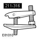 211-316 Separator, Ball Joint 211-316 Separator, Ball Joint | 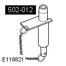 502-012 Alignment Pins, Subframe 502-012 Alignment Pins, Subframe |
General Equipment: Powertrain Jack
Removing
1. Raise and support the vehicle.
WARNING: Place secure stands under the vehicle.
2. Pump out a liquid from a tank of the amplifier of a steering.
3. Remove the front wheels. Refer to procedure: Wheel and tire (204-04 Wheels and tires, Removal and installation).
4. Remove the lower engine protection. Refer to procedure: Motor protection (501-02 Front body panels, Removal and installation).
5. Disconnect the left catalytic converter monitoring sensor electrical connector.
6. Disconnect the right catalytic converter monitoring sensor electrical connector.
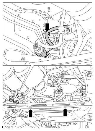
7. Release the catalytic converter monitoring sensor wiring harness.
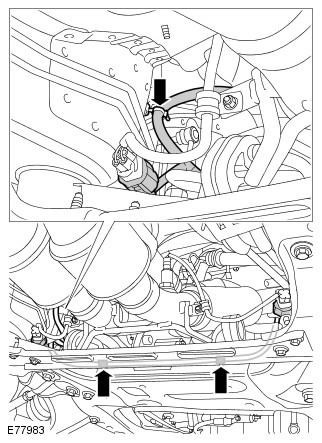
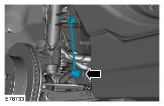
8. Disconnect both front stabilizer links from the lower suspension arm.
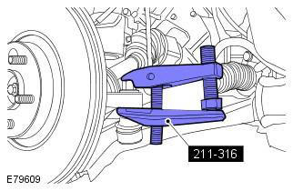
CAUTION: Do not allow the ball joint to rotate.
9. Using the special tool, release the left and right tie rod ball joints. Special tool: 211-316
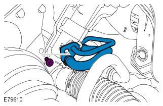
10. Disconnect pressure lines from the steering mechanism.
CAUTION: Be prepared to collect spilled liquid.
NOTE: Plug all openings.
11. Release the power steering lines.
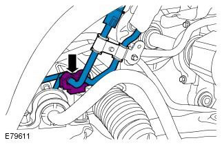
12. Disconnect the bottom section of a steering column from the steering mechanism.
WARNING: Install a new steering column swivel bolt.
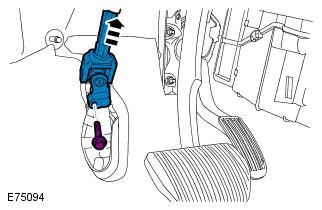
13. Release the lower catalytic converters.
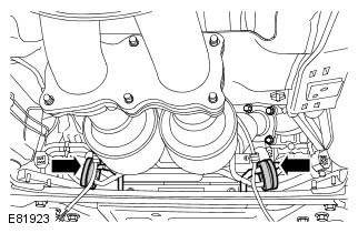
14. Release the left and right lower suspension arms.
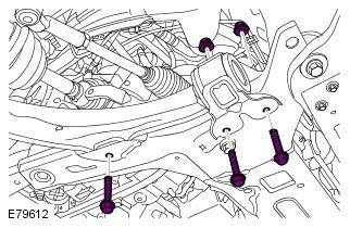
15. Disconnect the purge line from the subframe.
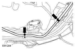
16. Release the fuel line.
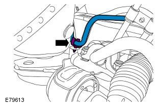
17. Support the subframe. General Equipment: Powertrain Jack
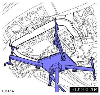
18. Remove the cross member of the front subframe.
CAUTION: Use new subframe bolts.
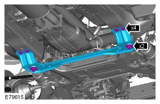
19. Lower the front subframe assembly.
Mark the position of the elements to facilitate subsequent installation. Use new subframe bolts.
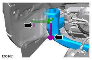
20. Remove the stabilizer.
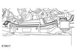
21. Lowering the subframe, release the left and right suspension arms and secure them to the side.
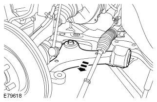
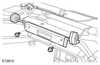
22. Remove the catalytic converter support bracket.
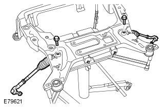
NOTE: Do not proceed with disassembly if the element is being removed only to gain access.
23. Remove the steering mechanism.
Installation
1. Install the steering gear. Tightening torque: 105 Nm
2. Using the special tool, support the subframe.
3. Raise the front subframe to allow the suspension arms and bolts to be installed.
CAUTION: Turn all bolts in by hand before final tightening.
4. With the subframe raised, install the left and right suspension arms.
5. Install the stabilizer.
6. Install the subframe cross member. Tightening torque: 45 Nm
CAUTION: Use new bolts.
7. Install 2 support brackets. Tightening torque: 25 Nm
CAUTION: Use new bolts.
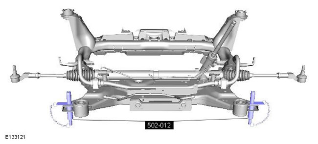
8. Install the front subframe. Special tool: 502-012. Tightening torque: Stage 1: 140 Nm. Stage 2: 240°
9. Install the catalytic converter support bracket. Tightening torque: 10 Nm
10. Install the fuel line.
11. Install the purge line.
12.
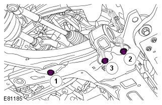
- Tighten bolt 1. Tightening torque: Stage 1: 140 Nm. Stage 2: 45°
- Tighten bolt 2. Tightening torque: 175 Nm
- Tighten bolt 3 with force. Tightening torque: 175 Nm
13. Fix catalytic converters.
14. Connect spherical hinges of the left and right steering drafts. Tightening torque: 105 Nm
WARNING: Use new nuts.
15. Attach pressure lines of the steering mechanism. Tightening torque: 25 Nm
16. Connect the stabilizer bar to the lower control arm and tighten to 55 Nm.
WARNING: Use new nuts.
CAUTION: Do not allow the ball joint to rotate.
17. Fix the wiring harness.
18. Connect a steering column to the steering mechanism. Tightening torque: 25 Nm
WARNING: Install a new steering column swivel bolt.
19. Connect and secure the catalytic converter monitoring sensor electrical connectors.
20. Screw in two bolts of fastening of a stretcher and remove a jack.
21. Install the lower engine protection. Refer to procedure: Motor protection (501-02 Front body panels, Removal and installation).
22. Install the wheels. Refer to procedure: Wheel and tire (204-04 Wheels and tires, Removal and installation).
23. Fill the power steering system with working fluid and remove air from the system. Refer to Procedure: Bleeding Power Steering System (211-00 Steering system - General information, General procedures).
24. Using only Land Rover's prescribed four-wheel alignment equipment, check and adjust the wheel alignment.
Comments on this article