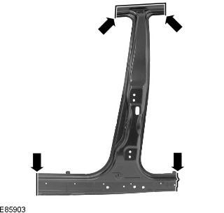
CAUTION: Rack Exterior Panel «B» to be soldered to the reinforcement element of the B-pillar using MIG spot soldering (which is made of BH300 heat treated steel) and internal reinforcing element of the bottom trim panel (which is made of DP600 steel (duplex steel)). Electric rivets/MIG spot welds should not be used.
NOTE: Rack Exterior Panel «B» serviced as a separate welded panel.
NOTE: An NVH element is fixed inside this panel; it is not serviceable on the new panel. If damaged, a new element will be required.
NOTE: If the outer panel of the rack «B» replaceable without strut reinforcement «B», if necessary, the butt connection of the upper section can be made down the rack.
Removing
1. When replacing the rack outer panel «B» the following items are removed:
- Front door
- Backdoor
- ceiling lining
2. For more information on this repair procedure, refer to the following sources: For more information, refer to the chapter: Body and Frame (501-26 Body Repairs - Vehicle Special Information and Approval Checks, Description and Operation) / Standard techniques used at the service station (100-00 General information, Description and principle of operation).
3. Remove the front door. For more information, see chapter: Front door (501-03 Lockable body elements, Removal and installation).
4. Remove the back door. For more information, see chapter: Tailgate (501-03 Lockable body elements, Removal and installation).
5. Remove the top and bottom door hinges from the rack «IN» (four bolts).
6. Remove the counter part of the front door lock from the pillar «B».
7. Remove the front seat. For more information, see chapter: Front seat (501-10 Seat, Removal and installation).
8. Remove the rear seat cushion. For more information, see chapter: Rear seat cushion (501-10 Seat, Removal and installation).
9. Remove the front seat belt retractor. For more information, see chapter: Front seat belt retractor (501-20A Seat belt system, Removal and installation).
10. Remove a covering of a ceiling. For more information, see chapter: Top trim - Vehicle not included: Tilting sunroof (501-05 Interior trim, Removal and installation) / Upper Trim - Included with the vehicle: Sunroof with tilting roof (501-05 Interior trim, Removal and installation).
11. Remove the left and right inner trim panels of the lower trim.
12. Remove the side impact sensor from the rack "IN". For more information, refer to the chapter: Strut Side Impact Sensor (501-20B Secondary restraint system, Removal and installation).
13. Remove the top side airbag module. For more information, refer to the chapter: Curtain side airbag module (501-20B Secondary restraint system, Removal and installation).
14. Remove the front and rear sections of the roof molding.
15. Remove the bottom trim panel outer molding.
16. Loosen and set aside the front section of the carpet.
17. Remove the rear carpet section.
18. Loosen and set aside the wiring harness that runs along the inside of the rack «B» and the inner panel of the lower harness.
19. Cut the old panel as shown following the dimensions shown to allow access to the rack reinforcement «B».
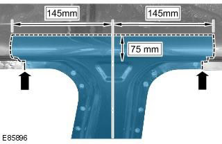
20. Cut off the old panel at the junctions with the bottom trim panel, providing an allowance for overlapping the new panel; use the new panel as a template.
21. Mill out the contact welding points.
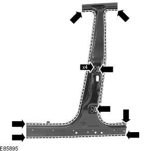
22. Separate the connections and remove the old panel, while also exposing the NVH element.
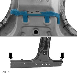
Installation
1. Align the new panel and lock it in position, overlapping the old panel remaining on the vehicle.
2. Cut the new and old panels on the bottom rail panel where the MIG butt joints are to be made.
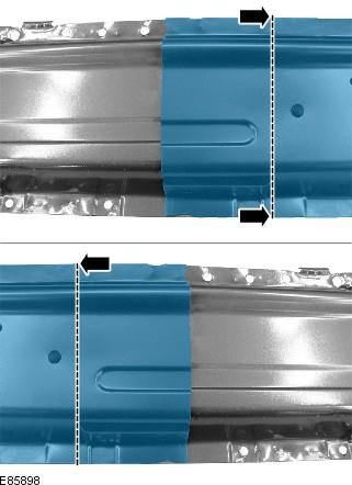
3. Cut the new and old panels at the top joint where the MIG butt joint is to be made.
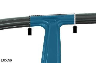
4. Remove the new panel and the remains of the old panel.
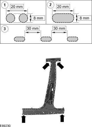
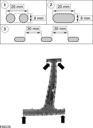
5. Cut holes in the new panel prepared for MIG soldering.
NOTE: The MIG welding holes should be spaced according to the intervals shown in the figure. Where this is not possible due to dents in the panel, a hole should be made at the location of the original spot weld.
6. Prepare the mating surfaces of the old and new panels.
7. If necessary, replace the NVH element.
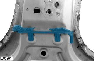
8. Apply adhesive to the NVH element.
9. Position the new panel in the desired location and secure it. Check position alignment. If it is correct, go to the next paragraph. If not, make any necessary adjustments and recheck before continuing.
10. Make tack welds for butt joints.
11. MIG solder through the holes.
12. Clean the tack welds.
13. Make MIG butt welds.
14. Clean all welds.
15. Installation of appropriate panels and mechanical elements performed in the reverse order of removal.
Comments on this article