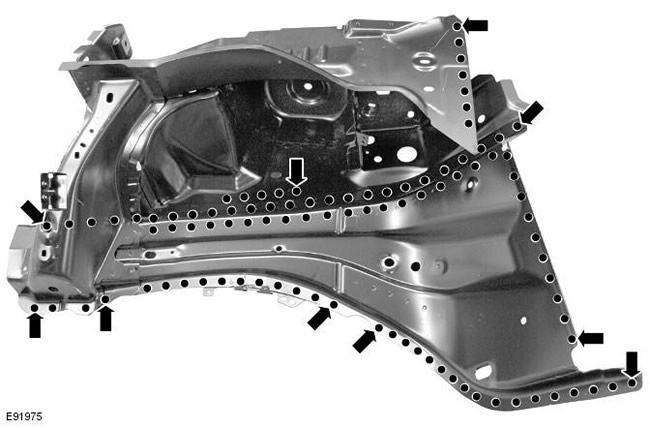
NOTE: The front spar and upper suspension mount assembly includes the end spar panel, wing apron panel reinforcement, front wing apron panel extension, lower wing apron panel, front spar and wing apron panel, and upper suspension mount.
NOTE: The service panel is not fully welded.
NOTE: The panel is serviced without its mounting studs.
Removing
1. In conjunction with the front side member and upper suspension mount assembly, replaces:
- front bumper cover
- Front bumper mount
- Hood latch panel
- Both front fenders
- Front bumper mount
- Upper fender apron panel
- Front spar
2. For more information regarding this repair procedure, see: For more information, refer to the chapter: Body and frame (501-26 Body Repairs - Vehicle Special Information and Approval Checks, Description and Operation) / Standard techniques used at the service station (100-00 General information, Description and principle of operation).
3. Remove the front side member. For more information, see chapter: Front side member (501-27 Repairs of sheet metal elements of the front end, Removal and installation).
4. Remove the upper fender apron panel. For more information, see the chapter: Top panel of the splash guard (501-27 Repairs of sheet metal elements of the front end, Removal and installation).
5. Remove the instrument panel. For more information, please refer to the chapter: Control panel - 2.2L Duratorq - Td4 (501-12 Instrument panel and console, Removal and installation).
6. Remove the bottom trim panel interior trim.
7. Remove the bottom trim of the rack «IN». For more information, please refer to the chapter: Rack Trim Lower Panel (501-05 Interior trim, Removal and installation).
8. Loosen and set aside the front carpet section.
9. Loosen and lay aside the insulation material on the outer baffle.
10. Left side: Remove the hood release handle.
11. Right side: Remove the vacuum brake booster. For more information, see chapter: Vacuum Brake Booster (206-07 Vacuum brake booster, Removal and installation).
12. Right side: Remove the pedal assembly.
13. Loosen and lay aside the rack wiring harnesses "A", partitions and spar.
14. Mill out the weld points.
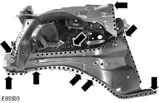
15. Separate the connections and remove the old panel.
Installation
1. Prepare a new panel in the areas of partial welding and MIG welding in these areas.
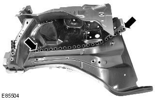
2. Prepare the connecting surfaces of the old and new panels.
3. Drill holes in the new panel for electric MIG welding.
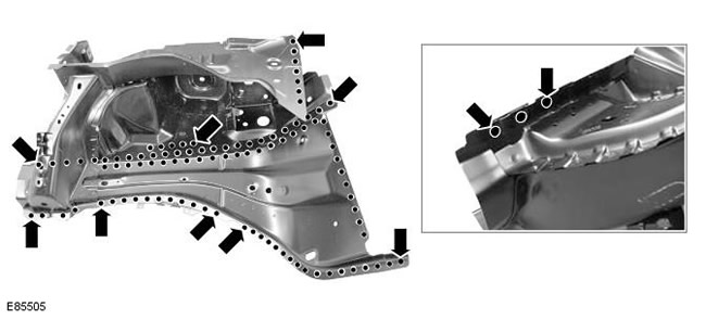
4. Attach the new panel and lock it in place. Check the reconciliation, if correct, go to the next step, if not, correct and check again before proceeding to the next step.
5. Welding with electric MIG rivets.
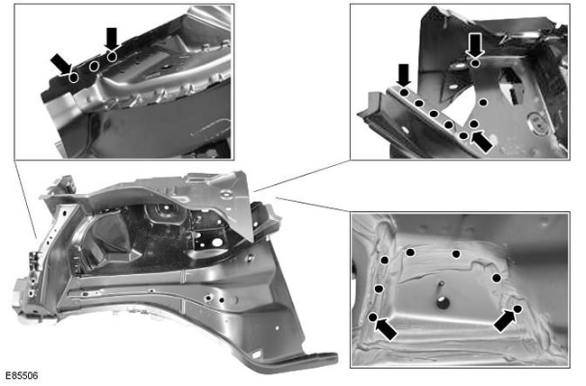
6. Welding with electric MIG rivets.
7. Install weld studs.
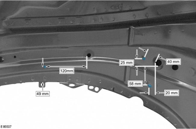
8. Install new dowel pins.
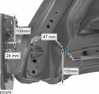
9. Clean all welds.
10. Reverse the removal procedure to install the appropriate panels and mechanicals.
Comments on this article