Dismantling
1. Disconnect "negative" battery terminal.
2. Remove the cylinder head.
ENGINE - MODIFICATION K, displacement 1.8, Front exhaust camshaft oil seal, Cylinder head gasket.
3. Remove the engine tray.
ENGINE - MODIFICATION K, volume 1.8, Front exhaust camshaft oil seal, Oil pan sealing.
4. Temporarily remove the LRT-12-144 cylinder liners. Do not rotate the crankshaft after removing the cylinder liner fasteners.
CAUTION: The cylinder head bolts must be laid out in the order in which they were installed on the engine.
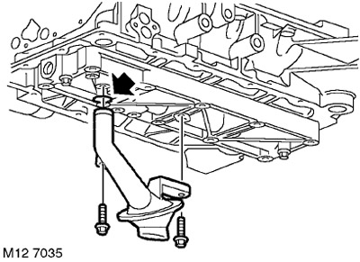
5. Turn away 2 bolts of fastening of an oil receiver to an oil distribution cover.
6. Remove the oil receiver with strainer.
7. Remove the O-ring from the oil receiver and discard it.
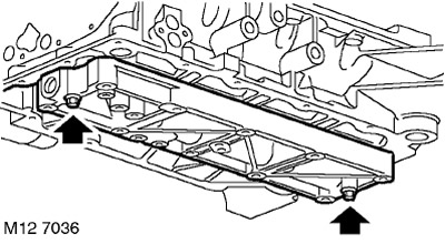
8. Turn away 2 nuts of fastening of an oil distribution cover to integral cover of radical bearings and remove a cover.
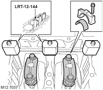
9. Install the LRT-12-144 cylinder liner fasteners using the nylon nuts included in the fastener kit. The base of the cylinder liners must not protrude above the cylinder surface.
10. Fix the cylinder liners with the cylinder head bolts by screwing the bolts into place (where were they before the disassembly).
11. Temporarily install the timing belt drive gear and the front crankshaft pulley, screw in the front pulley bolt with washer.
12. Turning the crankshaft clockwise, set the pistons of cylinders 2 and 3 to bottom dead center.
13. Mark the connecting rod caps.
14. Remove 4 fitting bolts (bolt that simultaneously acts as a pin) and remove the covers from the connecting rods of the 2nd and 3rd cylinders. Lay out the bolts and covers in the order they were installed.
15. Move the connecting rods away from the connecting rod journals and carefully slide the pistons up. Remove the liners from the connecting rods and connecting rod caps and dispose of them.
16. Turning the crankshaft clockwise, set the pistons of cylinders 1 and 4 to bottom dead center.
17. Mark the connecting rod caps.
18. Remove 4 fitting bolts (bolt that simultaneously acts as a pin) and remove the covers from the connecting rods of the 1st and 4th cylinders. Lay out the bolts and main caps in the order they were installed on the engine.
19. Move the connecting rods away from the connecting rod journals and carefully slide the pistons up. Remove the liners from the connecting rods and connecting rod caps and dispose of them.
Installation
1. Using a micrometer, measure the diameters of the connecting rod journals, measuring in four directions on each journal.
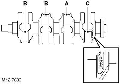
2. Write down the crankpin size group letter code located on the rear counterweight. Code designations are read from left to right, the first group refers to the 1st neck.
TECHNICAL CHARACTERISTICS, Engine - gasoline K1.8.
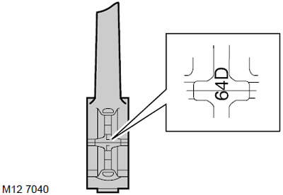
3. Write down the numbers of the size groups of the beds in the lower heads of the connecting rods. These are the numbers 5, 6 or 7, applied to the connecting rod caps. Choose the appropriate earbuds.
TECHNICAL CHARACTERISTICS, Engine - gasoline K1.8.
4. The colored markings on the edge of the liner indicate the thickness of the liner: YELLOW = thin liner, BLUE = medium thickness liner, RED = thick liner. If the inserts of two different color markings are to be installed on one neck, then a thicker insert is installed in the connecting rod cover.
5. Wipe the connecting rod journals and the surface of the beds in the lower head of the connecting rods.
6. Select the appropriate earbuds.
7. Lubricate the connecting rod journals and connecting rod bearings with clean engine oil.
8. Establish conrod loose leaves in a rod and in covers.
9. Carefully slide the connecting rod onto the neck, install the connecting rod cover, paying attention to the fact that the mounting grooves in the cover and in the body of the connecting rod should be on opposite sides and slightly tighten the connecting rod bolts.
10. Tighten the fitting bolts of the connecting rod cover:
- Stage 1: 20 N.m.
- Stage 2: 45°turn.
NOTE: With the cylinder head removed and the main bolts tightened, crankshaft rotation will be difficult.
11. Using a feeler gauge, measure the end play of the bottom head of the connecting rods on the connecting rod journal. The backlash value should be between 0.10 and 0.25 mm.
12. Wipe the oil distribution cover, oil receiver and mating surfaces.
13. Blow out the oil passages in the oil distribution cap and in the oil receiver.
CAUTION: If the threads are damaged, a new oil distribution cap must be installed. Thread repair inserts are not allowed (type Helicoil).
14. Temporarily remove the LRT-12-144 cylinder liners.
CAUTION: Do not rotate the crankshaft after removing the cylinder liner fasteners. The cylinder head bolts used to tighten the liner mounts must be laid out in the order in which they were installed on the engine.
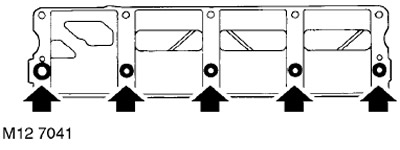
15. Apply a continuous bead of STC 4600 Sealant to the contours shown in the figure and spread it in a thin layer using a roller trowel.
WARNING: Assembly of prepared parts must be done immediately to prevent contamination of surfaces with applied sealant.
16. Install the oil distribution cover on the integral cover of the main bearings, fit the nuts and tighten them to a torque of 9 Nm.
17. Install the LRT-12-144 mounts on the cylinder liners and lightly tighten the bolts.
ATTENTION: The bolts used must be screwed into the same sockets in which they were on the assembled engine.
18. Lubricate a new O-ring with clean engine oil and fit onto the oil pickup tube.
19. Install the oil pick-up tube, screw in the bolts and tighten them to a torque of 12 Nm.
20. Turn away a bolt of fastening of a pulley of a cranked shaft, remove a pulley and a bolt with a washer.
21. Install the oil pan.
ENGINE - MODIFICATION K, volume 1.8, Front exhaust camshaft oil seal, Oil pan sealing.
22. Install the cylinder head.
ENGINE - MODIFICATION K, displacement 1.8, Front exhaust camshaft oil seal, Cylinder head gasket.
23. Attach "negative" battery terminal.
Comments on this article