Dismantling
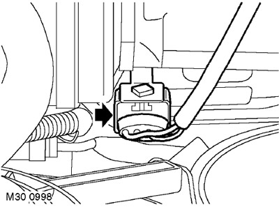
1. Release the oxygen sensor connector from the bracket on the left valve cover, disconnect the connector.
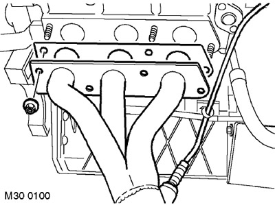
2. Turn away 4 nuts of fastening of the left final collector to a head of cylinders.
3. Remove the exhaust manifold and discard its gaskets.
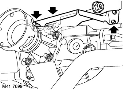
4. Turn away a nut of fastening of a heat-shielding screen to a distributing box.
5. Turn away a nut of fastening of a heat-shielding screen to a case of a shaft of a drive of the back bridge.
6. Turn away 2 bolts of fastening of a heat-shielding screen and remove the screen.
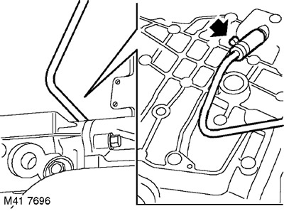
7. Disconnect the breather hose from the transfer case housing.
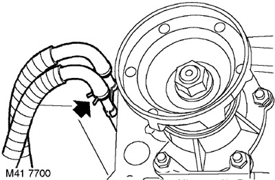
8. Loosen the clamp and disconnect the cooling system hoses from the transfer case.
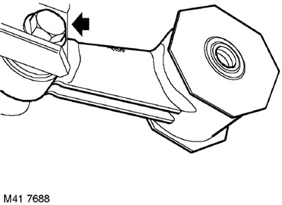
9. Turn away a bolt of fastening of the lower cross-section of the engine to an arm of a distributing box.
10. Remove the engine lower cross member. The 'TOP' label must be on top.
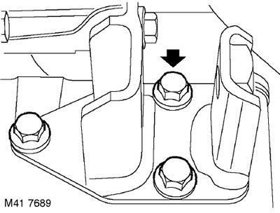
11. Turn out 3 bolts of fastening of an arm of a distributing box to the pallet.
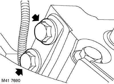
12. Turn away 2 bolts of fastening of an arm of a distributing box to a forward plate of the engine.
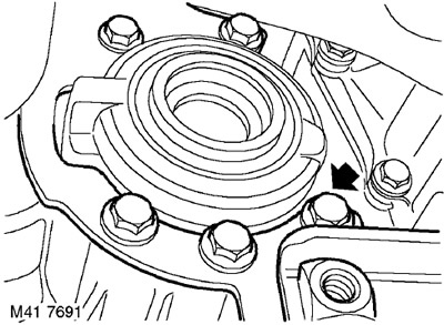
13. Turn out 5 bolts of fastening of an arm to a distributing box.
14. Remove the bracket.
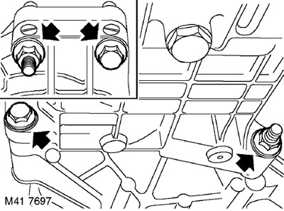
15. Turn away 4 bolts of fastening of a distributing box.
16. With the help of a partner, separate the transfer case from the gearbox and remove the transfer case.
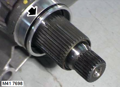
17. Remove the O-ring from the transfer case and discard it.
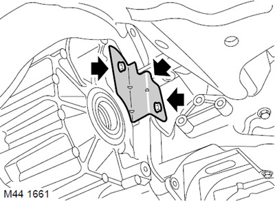
18. Turn out two bolts of fastening of a cover of the hatch of the hydrotransformer.
19. Remove the hatch cover.
20. Mark the mutual position of the drive disk and the torque converter for subsequent assembly.
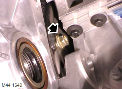
21. Turn away 4 bolts of fastening of a leading disk to the hydrotransformer.
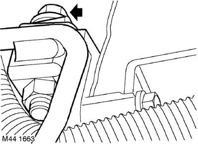
22. Turn away a bolt of fastening of a bracket of the hose of the system of cooling going on a distributing box. Remove the bracket.
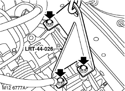
23. Turn out bolts of fastening of a lifting eye LRT-44-026 to a transmission and remove an eye.
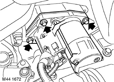
24. Remove the 3 bolts securing the starter to the gearbox, noting that the left one also serves to attach the crankshaft position sensor connector.
25. Remove the starter.
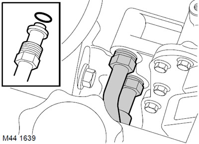
26. Disconnect the 2 fittings from the heat exchanger and discard the O-rings.
CAUTION: Always plug fittings and openings to keep dirt out of the system.
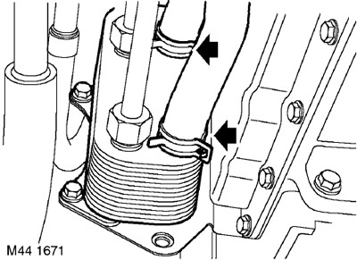
27. Loosen the two clamps and disconnect the cooling system hoses from the transmission heat exchanger.
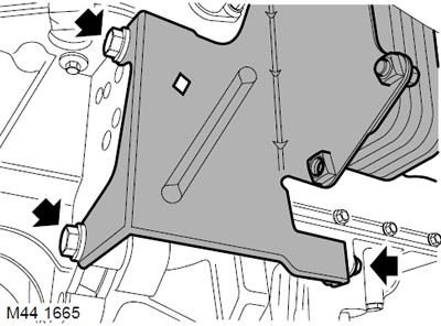
28. Turn away bolts of fastening of the heat exchanger.
29. Remove the heat exchanger for cooling the working fluid.
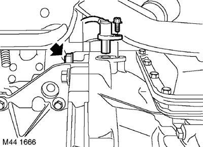
30. Turn away a bolt of fastening of the gauge of position of a cranked shaft to a transmission, release the gauge and take it aside.
31. Remove the bolt and nut securing the gearbox to the engine, located next to the crankshaft position sensor
32. Attach lifting eyes to the gearbox.
33. Attach the lifting equipment to the eyelets.
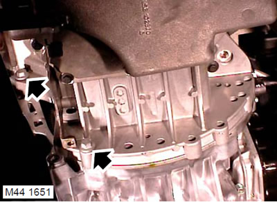
34. Turn away 2 bolts of fastening of a transmission to the engine.
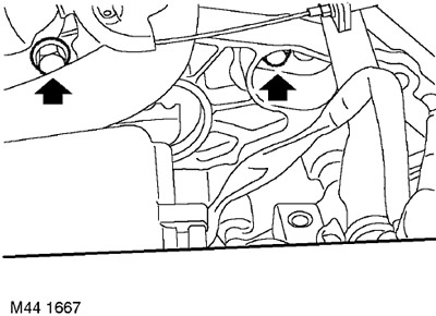
35. Remove the 2 upper bolts securing the gearbox to the engine.
36. Release the gearbox from the two guide pins.
37. Remove a transmission.
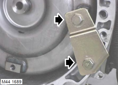
38. Install the torque converter fixing plate and secure with screws.
Installation
1. Remove the torque converter fixing plate.
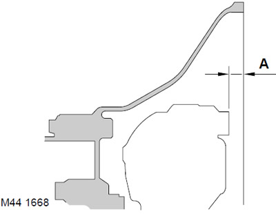
2. Check that the torque converter is fully seated on the oil pump drive by measuring dimension 'A' shown in the figure. Dimension A = 4 mm.
3. Wipe the mating surfaces of the engine and gearbox, dowel pins and pin sockets.
4. Install the gearbox.
5. Screw in bolts of fastening of a transmission to the engine and tighten them the moment of 85 Nm.
6. Remove lifting chains.
7. Wipe the crankshaft position sensor (CKP) and mating surfaces.
8. Install the crankshaft position sensor, screw in its mounting bolt and tighten to 9 Nm.
9. Install the heat exchanger, tighten the M12 bolts to 85 Nm, the M8 bolts to 25 Nm.
10. Connect the hoses to the heat exchanger.
11. Wipe the heat exchanger fittings.
12. Lubricate new O-rings with clean working fluid and install them on the heat exchanger hoses.
FILLING CAPACITIES, LIQUIDS AND OILS, Lubrication system.
13. Connect the heat exchanger hoses to the gearbox and tighten the union nuts to a torque of 18 Nm.
14. Clear a starter and interfaced surfaces of dirt.
15. Install the starter on the gearbox, bring the crankshaft position sensor connector bracket to the mounting point, screw in the bolts and tighten them to a torque of 45 Nm.
16. Fasten the lifting eyes LRT-44-026 to the gearbox on the gearbox using the bolts of the gearbox brackets.
17. Install the transfer box heat exchanger hose clamp, screw in the mounting bolt and tighten it to 25 Nm.
18. Align the position marks of the drive disc and the torque converter.
19. Screw in bolts of fastening of a leading disk to the hydrotransformer and tighten them with the moment of 45 Nanometers.
20. Wipe the converter hatch cover.
21. Install the hatch cover, screw in the bolts and tighten them to a torque of 9 Nm.
22. Clean the mating surfaces of the transfer case and gearbox.
23. Lubricate the new o-ring and install it in place.
24. With the help of a partner, install the transfer case.
25. Screw in the bolts securing the transfer case to the gearbox and pull together their mating surfaces without completely tightening the bolts.
26. Install the transfer case bracket and pull the mating surfaces together.
27. Finally tighten the bolts securing the transfer case to the gearbox. Tightening torque 80 Nm.
28. Finally tighten the transfer box bracket mounting bolts in the following order: tighten 5 bracket mounting bolts to the transfer box to a torque of 50 Nm, 2 bracket mounting bolts to the front engine mount - to a torque of 50 Nm, 3 bracket mounting bolts to the pallet - to a torque of 45 Nm.
29. Install the engine mount lower cross member with the 'TOP' mark up. Screw in the bolt, but do not completely tighten it.
30. Attach hoses of system of cooling and fix them collars.
31. Attach the breather hose to the transfer case.
32. Install the manifold heat shield and use your finger to tighten the nut that secures the rear axle drive shaft to the crankcase.
33. Screw in the bolts securing the heat shield to the transfer case bracket and tighten them to 9 Nm.
34. Fit the nut securing the heat shield to the transfer case and tighten it to 45 Nm.
35. Finally tighten the nut securing the heat shield to the rear axle drive shaft housing and tighten it to 25 Nm.
36. Wipe the exhaust manifold and mating surface on the cylinder head.
37. Install the exhaust manifold gasket.
38. Install the exhaust manifold, fit the nuts and tighten them to a torque of 45 Nm, starting from the center.
39. Connect the oxygen sensor connector and secure it to the bracket.
Comments on this article