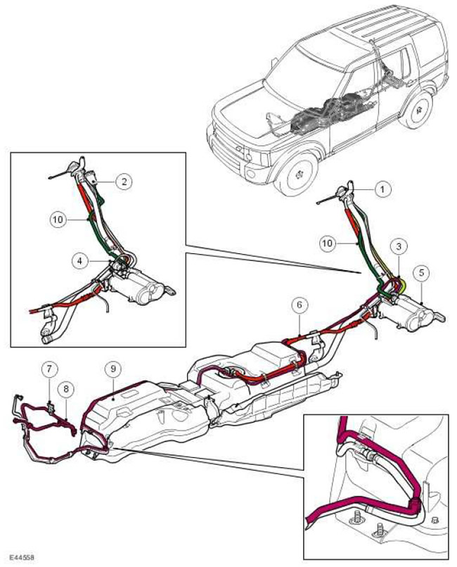
Location of system components

| Item name | Spare part number | Description |
| 1 | - | Fuel filler neck |
| 2 | - | DMTL pump filter (NAS only) |
| 3 | - | Ventilation hose connecting the fuel tank to the carbon adsorber |
| 4 | - | DMTL pump (NAS only) |
| 5 | - | Carbon adsorber |
| 6 | - | Fuel Tank Breather Hose |
| 7 | - | Purge valve |
| 8 | - | Purge hose |
| 9 | - | Fuel tank |
| 10 | - | Carbon canister ventilation hose (all models except NAS) or DMTL pump ventilation hose (NAS models only). |
General provisions
Evaporative Emission System (EVAP) 4.0 liter V6 engine reduces the amount of hydrocarbons released into the atmosphere from the fuel tank. The system includes a carbon adsorber, a purge valve, ventilation pipes and hoses. The ventilation pipes are connected to the system components using quick connectors.
Fuel vapors are formed in the fuel tank and the more, the higher the temperature of the fuel. Through the ventilation system of the fuel tank, fuel vapors freely enter the carbon adsorber. The ventilation system includes safety dampers that prevent fuel from spilling out when the car is turned over, and a fuel liquid phase separator (separator), installed inside the fuel tank and connected to the external environment through a ventilation hose. The breather pipe vents fuel vapors to the carbon adsorber through a tee mounted on the filler neck.
In NAS vehicles (for North America) fuel vapors formed during refueling freely enter the carbon adsorber.
In all vehicles that do not meet the NAS standard, fuel vapors displaced from the tank during refueling cannot enter the carbon canister, but are freely vented to the atmosphere through the filler neck.
Fuel vapors entering the adsorber are absorbed by activated carbon and remain in it. Since the capacity of the carbon adsorber is limited, it must be purged. Purging is carried out with the engine running, in which fuel vapors are burned.
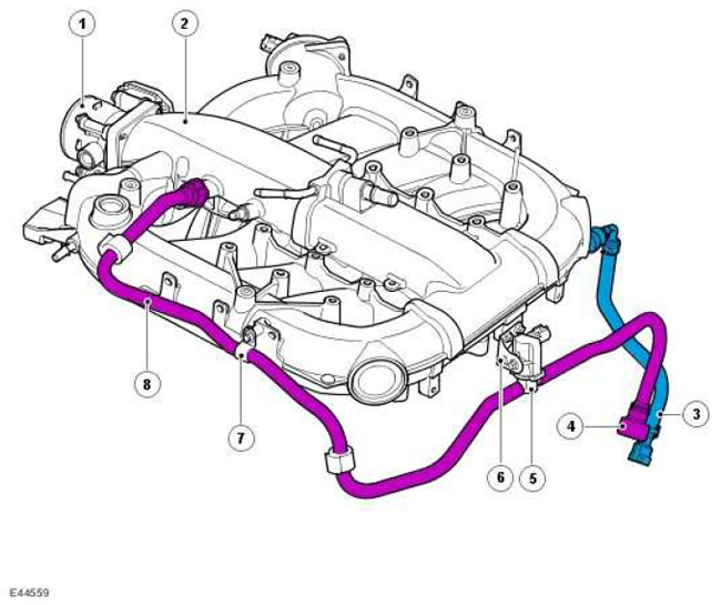
Purge valve and hoses

| Item name | Spare part number | Description |
| 1 | - | Electronic throttle |
| 2 | - | Air intake manifold |
| 3 | - | priming pump hose (for reference only) |
| 4 | - | Purge hose |
| 5 | - | Purge valve |
| 6 | - | bracket |
| 7 | - | hose clamp |
| 8 | - | Hose connecting manifold to purge valve |
The valve and purge hose are located on the air intake manifold, which is fixed to the top of the engine and is covered by a soundproof engine cover.
The purge hose connects the purge valve to the purge line, which runs parallel to the fuel line along the top of the fuel tank to the charcoal canister, using a quick connector on the right rear of the engine.
The purge hose is connected to the purge valve on the intake manifold and connected to the manifold via a hose clamp. A quick connector is used to connect the hose to the intake manifold.
The purge valve is mounted on a bracket at the rear of the intake manifold and secured with one bolt. The purge valve is a normally closed solenoid valve, i.e. it is closed when off. The purge valve is controlled by the ECM and opens cyclically to purge the canister depending on the engine's operating mode.
The valve is controlled by pulse-width modulation signals (PWM) with a frequency of 10 Hz. With such a high pulse frequency, the flow of purge gas entering the intake manifold is almost continuous. The duty cycle of the valve control pulses can vary from 5 to 100% (percent open state).
In the event of a feedback action to control fuel consumption, the ECM waits until the coolant temperature of the running engine rises above 40°C. Under these conditions, the engine runs smoothly and there is no excessive enrichment of the mixture. Duty cycle of control pulses (and purge speed) increases gradually because the concentration of fuel vapors is unknown (a sharp increase in the blowdown rate can lead to an excessive enrichment of the working mixture). The fuel vapor concentration is determined by the current closed-loop fuel trim that is performed to reach the setpoint for the mixture ratio. Once the concentration is determined, the purge rate can be quickly increased and the fuel injection volume can be pre-adjusted to compensate for the known purge volume and maintain the desired mixture.
On NAS vehicles, clean air enters the charcoal canister during purge through the DMTL pump vent and pump filter, and on other vehicles through the purge hose and trap.
The purge system in NAS vehicles does not have a pressure test point. In order to pressurize the purge hose, it must be disconnected from the purge valve connector under the bottom of the vehicle, in front of the fuel tank, and attach special equipment for crimping. This test checks to see if the purge hose from the fuel tank to the connector on the charcoal canister is good. A special pressure test tool is attached to the hose (for crimping).
Carbon adsorber
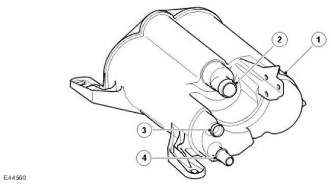
Carbon adsorber - excluding NAS vehicles

| Item name | Spare part number | Description |
| 1 | - | Carbon adsorber |
| 2 | - | The union of air ventilation of a coal adsorber |
| 3 | - | Purge hose fitting |
| 4 | - | The fitting of a hose of ventilation of a fuel tank on a coal adsorber |
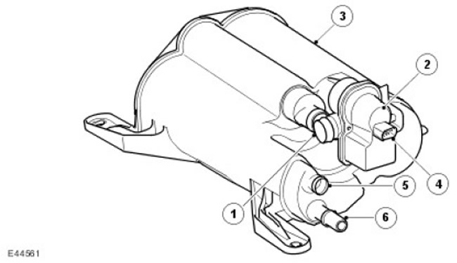
Carbon canister - NAS vehicles

| Item name | Spare part number | Description |
| 1 | - | Adsorber air vent fitting (via DMTL pump) |
| 2 | - | DMTL pump |
| 3 | - | Carbon adsorber |
| 4 | - | electrical connector |
| 5 | - | Purge hose fitting |
| 6 | - | Union of a hose of ventilation of a coal adsorber |
The carbon adsorber is located in the middle part of the body, in front of the spare wheel. With its rear part, it is attached with two bolts to the spare wheel bracket. There are two protrusions on the front of the canister that fit into the parking brake bracket.
In cars of the ROW standard, the adsorber volume is 1400 cubic meters. cm (85.4 in.3).
In cars of the NAS standard, the volume of the adsorber is 3000 cubic meters. cm (183 in.3).
There are three fittings on the canister, to which the canister air ventilation hose, purge hose and fuel tank ventilation hose are connected. On NAS vehicles, a DMTL pump is connected to the canister vent.
The adsorber contains activated charcoal. In the manufacture of activated carbon, a special oxygen treatment technology is used. Oxygen treatment opens up millions of microchannels between carbon atoms, dramatically increasing the active surface of the carbon and its absorption capacity. After this treatment, the coal becomes «activated». In order for a NAS vehicle to meet the environmental requirements of LEV 2, a higher quality charcoal is used in its canister.
Diagnostic Fuel Tank Leak Test System (DMTL)
Only for NAS vehicles
The use of the DMTL system in NAS vehicles is required by law. DMTL periodically checks the EVAP system for leaks (EVAP) and fuel tank (check is carried out with the ignition off).
The DMTL system includes all of the previously described EVAP system components plus two additional components: the pump and filter.
The DMTL pump is connected to the charcoal canister air vent. Pump includes electric air pump, PTC heating element (PTC), normally open valve and measuring washer (calibrated hole). The DMTL pump is only activated when the ignition is off and is controlled by the ECM. The ECM monitors the operation of the air pump and the function of the normally open valve.
The DMTL filter prevents the pump from drawing in dust during operation. The filter is located on top of the fuel tank filler pipe and is connected to the pump by a hose.
Operation of the DMTL system
To test the EVAP system and fuel tank for leaks, the ECM turns on the air pump and measures the pump's current draw. The ECM first sets the current reference value by pumping air into the atmosphere through a metering washer. Once the current reference is determined, the ECM closes the normally open valve, isolating the EvAp system from the outside. The purge valve is not energized and therefore remains closed. The pump no longer pumps air through the measuring washer, but supplies it to the EVAP system.
When the normally open valve closes, the load on the pump drops to zero. If the EVAP system is sealed, then the pressure in it will begin to rise, increasing the load on the pump and the strength of the current drawn by it. By measuring current strength and rate of change, the ECM determines whether there is a leak in the EVAP system or not.
During normal vehicle operation, the ECM turns on the heating element in the pump. This prevents the formation of condensation that interferes with correct current measurement.
Leaks in the system are divided into groups:
- Minor: equivalent to a hole with a diameter of 0.5 - 1.0 mm
- Major: Equivalent to a hole with a diameter of 1.0 mm or more.
- Vehicle speed is zero
- The crankshaft speed is zero
- barometric altitude (70 kPa (10.15 lbf/in2) according to the results of engine load calculations) does not exceed 3047 m above sea level.
- The outdoor temperature is in the range of 0-40°C.
- The carbon adsorber saturation coefficient does not exceed 2 (the value of the fuel vapor saturation coefficient can vary from -1 to +30). In this case, -1 corresponds to the complete absence of fuel vapors (0%), 0 corresponds to the stoichiometric ratio, and +30 corresponds to full saturation (100%).
- The fuel level in the tank is from 15 to 85% of the nominal volume
- Before the last stop of the engine, it worked for at least 10 minutes.
- The battery voltage is in the range of 10-15 V.
- At least 180 minutes have elapsed since the last engine shutdown.
- There are no recorded malfunctions of the components of the EVAP system, the system for measuring the outside air temperature and the fuel level in the tank
- The transfer case must be in high gear.
NOTE: A leak test can be performed using the T4. The use of this instrument eliminates the need for the above conditions and makes it possible to check the correct operation of the system and its components.
The ECM performs a minor leak test after every 14 major leak search cycles and after a refueling is registered.
After the leak test is complete, the ECM turns off the DMTL pump and opens (turns off the power) normally open valve.
If the tank filler cap opens during the leak test (there is a sharp drop in the current consumed by the pump) or refueling (fuel level rises), the ECM stops checking.
If the test reveals a leak, the ECM sets the appropriate DTC. If a leak is detected on two consecutive checks, the ECM illuminates the control system warning light on the next trip (MIL) in the instrument panel.
The duration of the check can be from 40 to 270 seconds, depending on the results obtained and the level of fuel in the tank.
Comments on this article