Lubrication system
NOTE: Oil cooler option shown.

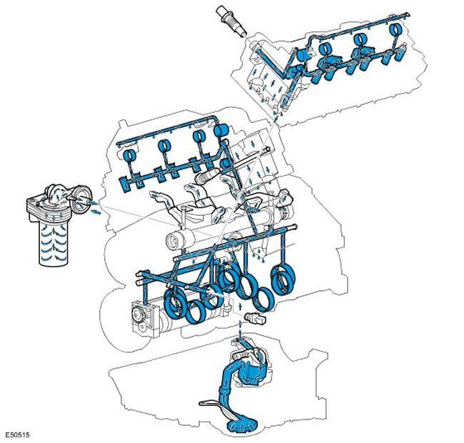
The lubrication system ensures that the entire oil flow is filtered and oil is supplied under pressure.
From the sump, through a strainer and an oil inlet pipe, oil enters the oil pump, driven by the intermediate shaft and having a built-in oil safety valve. The strainer and oil pick-up pipe prevent the passage of foreign particles through the oil pump and thus protect it from damage and prevent clogging of the oil passages. The oil relief valve in the oil pump opens when the oil pressure becomes too high and diverts the oil back around the pump.
Pressurized oil is pumped through an oil filter mounted on the oil pump housing. The lubrication system is designed in such a way that most of the oil flow is directed to the main oil gallery of the cylinder block, and less (determined by a restrictor in the oil filter housing) - to the oil cooler (in the presence of). The rest of the oil flow from the outside of the oil filter is combined with the return flow from the oil cooler (in the presence of), and then fed into the main oil gallery of the cylinder block.
The main oil gallery has channels through which oil is supplied to each cylinder head and main bearings. Cross-drilled holes in the crankshaft main bearings supply oil to the connecting rod bearings. Oil galleries in the cylinder head supply oil to the camshafts and hydraulic lash adjusters.
An oil pressure sensor is installed in the cylinder block, which determines the oil pressure before it enters the main gallery of the cylinder block. When a low oil pressure is detected, the control lamp on the instrument panel turns on.
Reduced pressure oil is supplied to each bank of cylinders through two block restrictors/cylinder head dowel pins, one at the front of the left bank and the other at the rear of the right bank. Then the oil enters the camshaft housing through a channel in the cylinder head bore and is fed through separate holes to the camshaft bearings and hydraulic tappet housings. The return oil from the cylinder head drains into the sump through the cylinder head bolt channels.
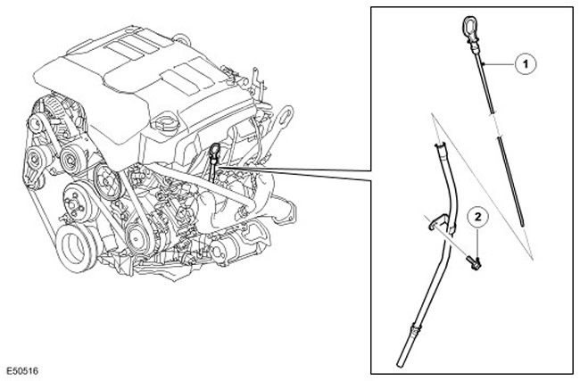
Oil dipstick

| Item name | Spare part number | Description |
| 1 | - | oil dipstick |
| 2 | - | dipstick tube |
The oil dipstick is located on the left side of the cylinder block in a tube inserted into the oil pan. The two holes at the end of the dipstick correspond to the minimum and maximum oil levels. The difference between these two marks is approximately 1.5 liters.
Comments on this article