General information
The oil is pumped out of the reservoir in the oil pan and supplied under pressure by the oil pump. At the outlet of the oil pump, the oil is filtered and distributed through the internal oil supply channels.
Lubrication of all moving parts is carried out by supplying oil under pressure, or by spraying oil. The pressurized oil also powers the hydraulic lifters and timing chain tensioners.
The engine is lubricated by a forced oil circulation system using a full-flow oil filter. The oil cooler forms a single unit with the oil filter and fuel cooler and is located in the center of the cylinder block between the two cylinder banks. Engine oil cooling is provided by the engine cooling system. This eliminates the need for an additional separate oil cooler.
The fuel cooler, which is part of the oil filter housing, also uses engine coolant. In addition, there is an additional fuel cooler in the fuel tank return line.
The oil returns to the sump by gravity. Large drain holes in the cylinder heads and cylinder block provide rapid oil return, reducing oil volume requirements and allowing accurate oil quantification soon after the engine has stopped.
Oil is added to the system through the oil filler neck on the right-hand camshaft cover.
With the exception of the pump and dipstick, all parts of the lubrication system are mounted on the oil pan.
Oil intake
A cast composite oil pick-up tube is immersed in the oil reservoir and provides oil to the oil pump in any allowable position of the vehicle. The crown shape of the inlet allows oil to be supplied even if the oil pan is deformed (for example, as a result of a blow to "earth"). Inlet mesh prevents solid particles from entering the lubrication system.
Oil pump

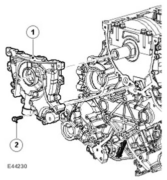
| Item name | Spare part number | Description |
| 1 | - | Oil pump |
| 2 | - | Bolt |
The gear type oil pump is bolted and pinned to the front of the cylinder block. The sealing of the connection is provided by a rubber gasket recessed into the oil pump housing. The inlet and outlet ports of the pump are aligned with the oil grooves in the ladder structure.
The working element of the pump is an eccentric rotor driven directly by flat surfaces on the crankshaft. Built-in pressure relief valve regulates oil pump outlet pressure to a fixed pressure of 4.5 bar (65,25 psi).
The front crankshaft oil seal is located in the oil pump housing and is mounted in such a way that its front surface is deepened by 1 mm in relation to the machined front surface of the oil pump.
NOTE: The stuffing box must not be pressed into the hole until it stops, as this will block the drain channels.
Oil filter
The oil filter is a replaceable cartridge mounted on an adapter in the center of the V-row. An internal bypass system allows oil to bypass the filter if it is clogged.
NOTE: During repairs, care must be taken when removing the filter to minimize the amount of oil spilled between the V-shaped cylinder blocks and into the camshaft covers.
- Do not use compressed air / power tool
- Loosen the oil filter cap 4-5 turns.
- Wait at least 1 minute for the oil to drain out.
- Remove the cap, taking care to minimize the amount of spilled oil.
- Replace the oil filter element in the cap (it can only be installed on one side).
- Replace the cap and tighten it to the correct torque.
Oil pressure sensor

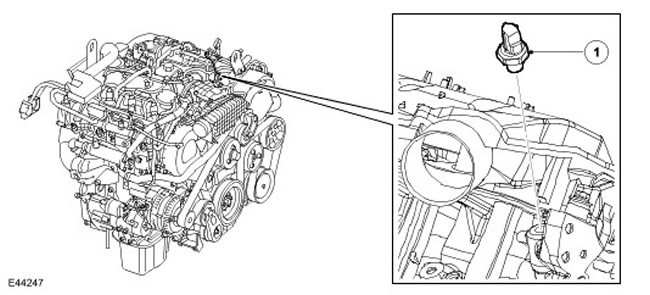
| Item name | Spare part number | Description |
| 1 | - | Oil pressure sensor |
The oil pressure switch, located in the V-row in front of the left cylinder head, grounds the instrument panel input when oil pressure is present. The sensor is triggered in the pressure range from 0.15 to 0.41 bar (2.2 to 5.9 psi).
Oil dipstick
The oil dipstick is located centrally along the left side of the oil pan in a tube inserted into the ladder structure. The two holes at the end of the dipstick correspond to the minimum and maximum oil levels. The difference between these two marks is approximately 1 liter (1 US quart).
Comments on this article