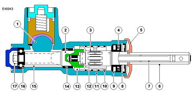
| Item name | Spare part number | Description |
| 1 | - | Rail |
| 2 | - | gear shaft |
| 3 | - | Sleeve |
| 4 | - | oil sleeve |
| 5 | - | Dirt seal |
| 6 | - | input shaft |
| 7 | - | Torsion |
| 8 | - | Retaining ring |
| 9 | - | Oil seal |
| 10 | - | PTFE ring |
| 11 | - | Cast steering gear housing |
| 12 | - | grooves |
| 13 | - | Pin - between gear shaft and sleeve |
| 14 | - | Oil seal |
| 15 | - | gear shaft |
| 16 | - | Bearing |
| 17 | - | Gear Shaft Nut |
The hydraulic distributor is part of the steering mechanism. Hydraulic valve provides maximum power amplification (e.g. when parking), when minimal effort is required to turn the steering wheel.
The distributor gear housing is part of the main casting of the steering gear housing. The gear housing has four holes for connecting the inlet pipe from the power steering pump, the outlet pipe to the reservoir, and the inlet pipes on each side of the cylinder piston.
The hydraulic distributor consists of a sleeve, an input shaft, a torsion bar and a pinion shaft. The hydraulic distributor is mounted on the same axis as the gear shaft, which is connected to the steering column through the input shaft. The hydraulic distributor parts are located in the steering gear housing, which is closed with a sealed cover.
The sleeve is located in the main gear housing. Three annular grooves are made along its outer diameter. PTFE rings are installed between the grooves, which serve as seals between the hole and the gear housing. Radial holes are drilled through the wall of the sleeve in each annular groove. The hole in the sleeve is bored to fit the size of the input shaft. Six grooves are made in the sleeve hole at equal distance from each other. The ends of the grooves are closed and do not reach the end of the sleeve. Radial holes are drilled in each groove of the sleeve.
The input shaft has two machined surfaces on the outer end designed to hold the steering column intermediate shaft clamp. The machined surfaces ensure that the layshaft is correctly positioned at the optimum angle. The inner end of the intermediate shaft has a protrusion that fits into the groove of the gear shaft. The position of the lip in the slot allows for a slight relative rotation of the input shaft and the pinion shaft before the lip touches the slot wall. This ensures the operation of the steering in manual mode without overloading the torsion bar in the event of a power failure. Longitudinal grooves are made along the circumference of the central part of the input shaft at regular intervals. The grooves are arranged alternately around the input shaft.
The torsion bar is attached to the inside of the input shaft and is fixedly mounted on the pinion shaft. The torsion bar is connected to the input shaft by a drive pin. In the central part, the torsion bar has a smaller diameter than at the ends. The smaller diameter allows the torsion bar to twist under the torque applied to the steering wheel, in accordance with the grip of the tires on the road surface.
The pinion shaft has an upper protrusion in the center that engages with a protrusion on the steering rack. The groove machined in the upper end of the pinion shaft includes a ledge on the input shaft. The pinion shaft is located in the gear housing and rotates on ball-roller bearings.
Comments on this article