Special tool
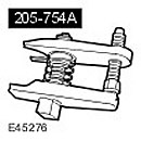 Ball joint puller 205-754
 |
Removing
All cars
1.
WARNING: It is forbidden to carry out work on a vehicle supported only by a jack. Be sure to place secure supports under the vehicle.
Raise and support the vehicle.
2. Disconnect the ground wire from the battery. For more information, refer to Specification
3. Remove the front wheels.
4. Remove the bridge stocking. For more information refer to Axle tube (47.10.42)
5. Remove the front axle cross member. Turn out four bolts.
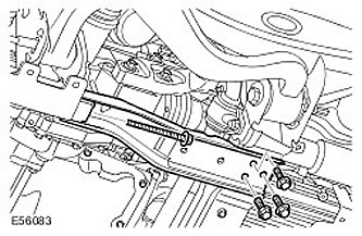
6. Disconnect the left brake hose bracket from the steering knuckle. Turn out a bolt.
7.
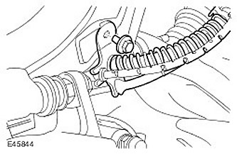
CAUTION: Do not damage the ball joint boot. Damage to the protective cover leads to premature failure of the hinge.
Using the special tool, disconnect the left tie rod end ball joint from the steering knuckle. Loosen and discard the nut.
8.
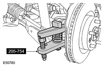
CAUTION: Do not damage the ball joint boot. Damage to the protective cover leads to premature failure of the hinge.
CAUTION: Excessive deflection can damage the lower arm ball joint. It is necessary to constantly support the steering knuckle. Do not allow the steering knuckle to hang on the lower control arm. Failure to do so may result in vehicle damage.
Using the special tool, disconnect the left upper control arm ball joint. Loosen and discard the nut.
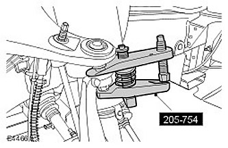
9. Disconnect the left axle shaft from the axle assembly.
- Remove the snap ring and discard it.
- Using a suitable clamp, hang the left axle shaft.
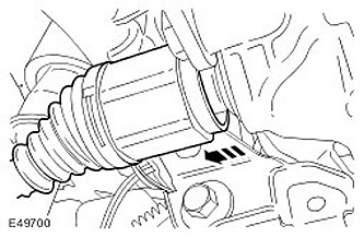
10.
CAUTION: Mark the position of the propshaft flange in relation to the pinion flange.
Disconnect the propeller shaft from the drive flange on the front axle.
- Remove 6 bolts and washers. Discard the bolts.
- Using a suitable clamp, secure the driveshaft end plate.
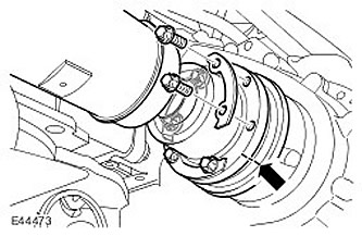
11.
CAUTION: Before disconnecting or removing any components, make sure that the area around the contact surfaces and connections is clean. Close all open connections to avoid contamination of the system.
Disconnect the ventilation line. Release the clamp.
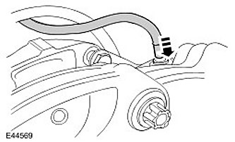
Vehicles manufactured before 02.2007
12.
NOTE: If a new axle is being installed, a new ventilation line must also be installed.
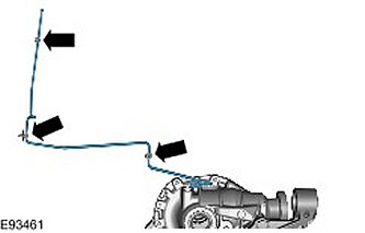
Remove the ventilation line in front of the bridge and discard it. Release from the three clamps.
All cars
13. Using a transmission jack, support the front axle assembly.
14. With the help of someone else, remove the front axle assembly.
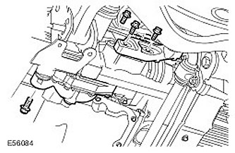
- Remove and discard the three rear axle mounting bolts.
- Turn out a forward bolt of fastening of the forward bridge.
Installation
All cars
1. With assistance from others, install the front axle assembly.
2. With assistance, align and secure the front axle assembly.
- Tighten the M14 bolt to 105 Nm.
- Tighten the three new axle mounting bolts in front of it to 80 Nm, and then tighten the bolts another 60 degrees.
Vehicles manufactured before 02.2007
3.
NOTE: If a new axle is being installed, a new ventilation line must also be installed.
Install a new ventilation line in front of the bridge. Fasten with clips.
All cars
4. Under connect the ventilation line.
5.
NOTE: New bolts must be installed.
Fix the cardan shaft on the drive flange and in front of the axle.
- Remove and discard clamp.
- Stage 1: Tighten the bolts to 45 Nm.
- Stage 2: Tighten the bolts another 90 degrees.
6. Install a new retaining ring on the left axle shaft. Remove and discard clamp.
7.
NOTE: Do not fully insert the axle shaft until the oil seal guard has been removed.
Attach the left axle shaft to the axle assembly.
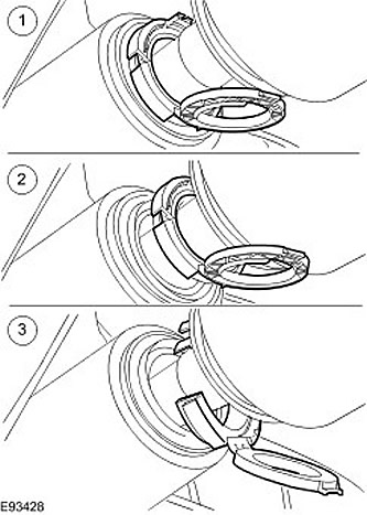
- 1) Open the axle shaft seal protection and install the axle shaft.
- 2) Release the axle seal protection from the axle seal.
- 3) Remove the axle seal protection.
- 4) Fully install axle shaft.
- 5) Make sure the circlip is fully seated and is holding the axle shaft.
8.
NOTE: Install new nut.
Attach the left upper control arm to the steering knuckle. Tighten the nut to 70 Nm.
9.
NOTE: Install new nut.
Under connect the ball joint of the left tie rod end to the steering knuckle. Screw on a new nut and tighten it to 76 Nm.
10. Install the left brake hose bracket to the steering knuckle. Tighten the bolt to 22 Nm.
11. Install the front axle cross member. Tighten the four bolts to 115 Nm.
12. Install the bridge stocking. For more information refer to Axle tube (47.10.42)
13. Install wheels. Tighten the wheel nuts to 140 Nm.
14. Connect ground wire to battery. For more information, refer to Specification
Comments on this article