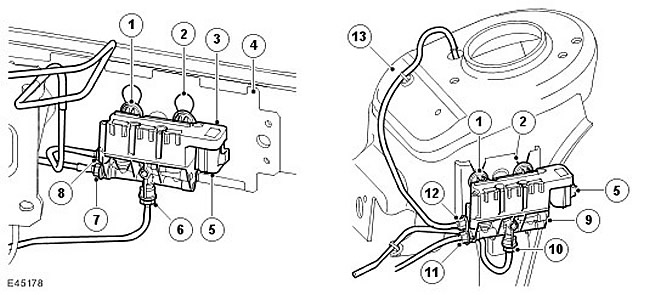
| Item name | Spare part number | Description |
| 1 | - | Rubber anti-vibration mounts (3 pcs.) |
| 2 | - | Mounting slots |
| 3 | - | Front valve block, valves and solenoids assy |
| 4 | - | Front bumper mount |
| 5 | - | electrical connector |
| 6 | - | Air Line Connection for Left Air Spring Module |
| 7 | - | Air inlet/outlet connection |
| 8 | - | Air line connection of the right air shock absorber module |
| 9 | - | Rear valve block, valves and solenoid assembly |
| 10 | - | Air line connection of the right air shock absorber module |
| 11 | - | Air inlet/outlet connection |
| 12 | - | Air Line Connection for Left Air Spring Module |
| 13 | - | Rear suspension head |
The front and rear valve blocks are of the same design. They regulate the air supply and its distribution between the front or rear air shock absorbers. The difference between the two valves lies in the connections from the valve blocks to the left and right air springs, as well as the size of the valves. The valve block must be installed on the corresponding bridge. Installing the wrong valve block will not cause the air suspension system to fail, but it will cause lift and release sluggishness and uneven front and rear axle lift and lower.
The front valve block is fixed to the right side of the front bumper mount assembly. The valve block has three mounting brackets under which rubber anti-vibration mounts are installed. Rubber supports are installed in the bumper mounting grooves. The valve bracket is inserted into the holes above the slots and is pulled down into its seat in the slots.
The rear valve block is located on the front side of the left rear suspension head. The valve block has three mounting brackets with rubber anti-vibration mounts that fit into the bracket with three grooves. The bracket is attached to the left side of the chassis. Vibration-proof rubber mounts are located in the V-shaped slots and are pulled down to their seat in the slots.
The front and rear valve blocks have three pneumatic connecting pipes with Voss fittings. One connection is for air inlet/outlet to the receiver valve block. The other two connections are designed to create pressure in the left and right elastic pneumatic elements.
Each valve block contains three solenoid valves: two damper valves and one bypass valve. The air suspension control unit controls each solenoid valve individually. Electromagnets have a resistance of 2 ohms at 20°C (68°F).
Damper valves
The shock absorber valves control the air inlet and outlet for the individual air springs. When the solenoid is not energized, an internal spring holds the damper valve in the closed position. When current flows through the electromagnet, the valve opens, and air can enter or exit the elastic pneumatic element.
Bypass valves
The bypass valve provides connection of two pneumatic elastic elements installed on one bridge. When there is no current flowing through the bypass valve solenoid, air cannot flow from one air spring to another. If current flows through the electromagnet, the valve spool moves and air can flow from one pneumatic elastic element to another. This increases the mobility of the wheels and improves comfort when driving at low speeds.
Comments on this article