Removing
WARNING: Before carrying out any work on the SRS system, read the related information carefully.
CAUTION: Always disconnect both wires from the battery before working on the SRS system. Disconnect the cable first "masses". Never connect the battery with reverse polarity.
WARNING: Set wheels straight ahead. Failure to follow this instruction may result in damage to parts.
ATTENTION: The correct installation of the movable contact group is carried out if a yellow marker is visible in the window on the surface of the clock spring. If the marker is not visible, carefully turn the movable contact group. If the resistance to rotation begins to increase before the marker appears, change the direction of rotation to avoid damage to the part.
NOTE: test sample.
NOTE: If SRS system components need to be replaced, the barcode of the new part must be recorded.
1. Fully extend the steering column for easy access.
2. Secure the SRS system.
For more information, refer to Standard Techniques Used in a Service Station.
3. Remove the steering wheel.
For more information refer to Steering wheel (57.61.01)
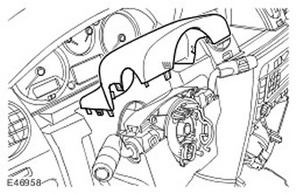
4. Remove the top casing of a steering column.
- Release 6 clips.

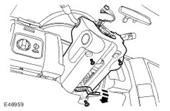
5. Remove the lower casing of a steering column.
- Remove 3 Torx head screws.
- Loosen the steering column adjustment lever.

6.
ATTENTION: Do not disassemble the movable contact group; it contains no serviceable parts and must be replaced as an assembly.
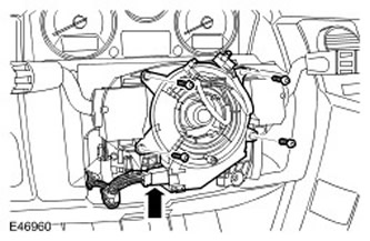
Remove the movable contact group.
- Disconnect the two electrical connectors.
- Remove 4 screws.

Installation
1.
ATTENTION: The correct installation of the movable contact group is carried out if a yellow marker is visible in the window on the surface of the clock spring. If the marker is not visible, carefully turn the movable contact group. If the resistance to rotation begins to increase before the marker appears, change the direction of rotation to avoid damage to the part.
Put the elements back in place. acting in reverse order.
Comments on this article