Introduction
CAUTION: Do not use any other heat shrink hose other than the recommended taped heat shrink hose mentioned in the repair procedure.
This document is intended to provide information on quick and efficient minor repairs to connectors or cables using approved methods and a harness repair kit. Repairs are only permitted for cables and connectors with mechanical, not electrical, damage. In addition, this procedure can be applied in cases where the degree of damage can be clearly identified and repaired.
The high quality of repair is determined by the thoroughness and accuracy of the performer.
Warning:
At the time of the initial release of the Harness Repair Manual, there are no approved repair procedures for the following circuits:
- Any MOST network harnesses.
- Airbag Deployment Circuits (SRS).
- Connecting wire assemblies exclusively used for safety-critical circuits, such as anti-lock brake circuits (ABS) and thermocouples. An example is ABS wheel speed sensors with molded connectors.
- Shielded cables, wires and wiring harnesses.
If any wire harnesses with bad contacts in the electrical connectors or wires from the above circuits are the cause of the problem, new components must be installed.
Repair kit
CAUTION: If the repair procedure calls for the use of an adhesive heat shrink sleeve, heat the sleeve to the melting temperature of the adhesive to seal the seal. Do not overheat the adhesive heat shrink sleeve to avoid damage to the wire harness insulation.
Wiring harness repair kit contains:
- Terminated wire harnesses in various sizes and types
- Three standard sizes of butt connectors
- Sleeve set with color coded cables
- Two sizes of adhesive heat shrink sleeves
- Crimping pliers
- Wire cutter and wire stripper
- Handle and tips of the tool for extracting contacts from electrical connectors
You will need a suitable heat source to heat shrink the sleeves.
The only approved harness repair tools are the insulated Diamond Grip electrical connector terminals. Butt connectors not only fix the wire, but also the insulation, providing a very secure connection.
If the electrical connector pins are not included in the harness repair kit, the repair is NOT authorized, in which case a new harness must be installed.
Terminated Wire Harnesses and Butt Connectors
All Terminated Wire Harnesses and Butt Connectors in the Harness Repair Kit are stored in bags that can be resealed after use. Each bag is labeled with the number of the parts stored in the bag. Each storage compartment in the harness repair kit is labeled with the appropriate part number. Make sure that the terminated wire harnesses and connectors are not mixed up: it is recommended to open one bag at a time and reseal the bag before opening the next one. Also, place the bag in the compartment of the case with the corresponding part number.
Terminated wire harnesses are available with one of three colors of insulation - red, blue or yellow. The colors do not refer to a specific circuit, but indicate the size of the wire in the bundle. See the mapping table in the Repair Method section.
Butt connectors are also available in red, blue and yellow to match the insulation color of the terminated wire harness.
Terminated wiring harness
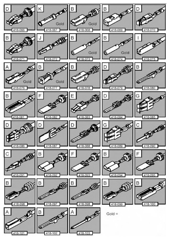
The figure shows:
- Terminated Wire Harnesses Included in Wire Harness Repair Kit
- Terminated Wire Harness Part Number
- Letter indicating the extractor tip to be used to remove this type of contact from the electrical connector
- Gold Plated Electrical Connector Contacts
Some terminated wire harnesses have seals that are installed on the insulation for use where a sealed connector is required. If the sealed contact has been removed, a sealed, terminated wiring harness must be used to prevent moisture ingress.
CAUTION: If the repair procedure calls for the use of an adhesive heat shrink sleeve, heat the sleeve to the melting temperature of the adhesive to seal the seal. Do not overheat the adhesive heat shrink sleeve to avoid damage to the wire harness insulation.
The harness repair kit includes two sizes of heat shrink sleeves. Each shrink sleeve contains a sealing adhesive. These sleeves must always be used when connecting wire harnesses or electrical connector pins. The smaller diameter shrink sleeve is used with red and blue butt connectors, while the larger diameter sleeve is used with yellow butt connectors.
To simplify and speed up the procedure, some terminated wire harnesses may already be partially stripped at the splice side. If it is necessary to strip the insulation on the cable for repair, see the comparison table for the length of the insulation to be stripped.
On the image "Terminated wiring harness" shows the type of electrical connector pin, the part number of the terminated wire harness, and the letter of the extractor tip that should be used to remove the pin from the connector housing. In addition, the gold-plated contacts of the electrical connector are marked, all the rest are not gold-plated, but tinned.
Identification Sleeves for Cable Harnesses
The harness repair kit contains several colored sleeves to keep the identification of the harness cables in the terminated harness. Slide the correct color sleeve over the terminated harness insulation as close to the electrical connector as possible so that the base color of the harness cable is closest to the electrical connector.
For example, if the color of the original harness cable is pink with a black line, put the pink harness cable identification sleeve over the terminated harness, then put on the black sleeve after that, and slide both sleeves along the harness cable to the electrical connector terminal.
Handle and tips of the contact extraction tool
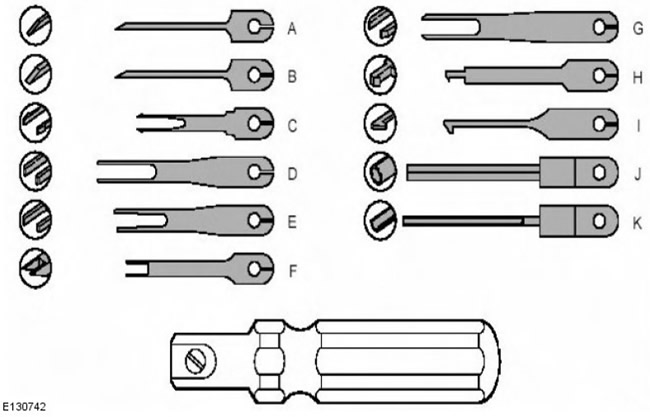
An extractor handle with a correct tip is used to remove a contact from an electrical connector. Each lug in the harness repair kit is marked with an identification letter from A to K. Each lug is specifically designed to remove a specific type of pin from an electrical connector. It is not recommended to use any other tools, as there is a possibility of damage to the connector. The tip is attached to the handle with a screw, which securely fixes the tip and at the same time makes it easy to replace it.
Wire stripper
The movable clamps are equipped with a multi-hole adjustment knob. By turning the handwheel and inserting the cable into a hole of the corresponding diameter, the clamping pressure is automatically adjusted. Please note that some wire harnesses may have stiffer insulation and will require slight adjustment of the handwheel position for a good cut, but be careful not to damage the wire.
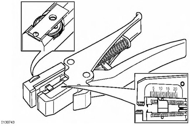
By pressing on the outer edges of the latch, the adjuster can be moved up and down the clips. This shortens and lengthens the length of the cable insulation trimmed in a terminated wire harness or wire in a wire harness. The regulator has a position indicator with a graduated scale, which allows you to set the length of the insulation trim in millimeters. The insulation trim value is shown in the comparison table.
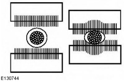
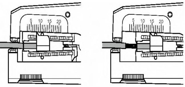
The illustration shows a wire stripper and a wire harness correctly clamped into the clamps. The wire cutter is located on the outside of the fixed clamp.
Cable correctly clamped in the wire stripper
Crimping pliers
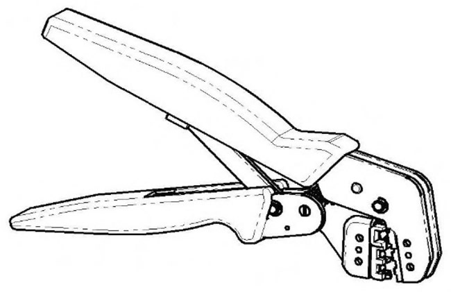
Crimping pliers are equipped with movable and fixed jaws, as well as crimping zones in three sizes. Zones are labeled with a red, blue, or yellow dot to represent the three colors of terminated wire harnesses and butt connector colors.
Parts list
| Description | Detail number | Quantity |
| Wiring Harness Repair Kit | 418-S065 | 1 |
| Terminated wiring harness | from 418-066 to 418-103 inclusive | 10 pieces. |
| Adhesive shrink bag: small diameter | 418-104 | 25 pcs. in the package |
| Adhesive shrink bag: enlarged diameter | 418-105 | 10 pieces. in the package |
| Carrying Case Assembly: Carrying Case, Lid, Inner Lid, Base, Insert, Foam Tray Pads | 418-106 | 1 |
| Butt Connector - Red | 418-107 | 50 pcs. in the package |
| Butt connector - blue | 418-108 | 50 pcs. in the package |
| Butt connector - yellow | 418-109 | 20 pcs. in the package |
| Extractor handle | 418-110 | |
| Tip pack includes two spare screws plus | 418-S111 | |
| Tip A | 418-118 | |
| Tip B | 418-119 | |
| Tip C | 418-120 | |
| Tip D | 418-121 | |
| Tip E | 418-122 | |
| Tip F | 418-123 | |
| Tip G | 418-124 | |
| Tip H | 418-125 | |
| Tip I | 418-126 | |
| Tip J | 418-127 | |
| Tip K | 418-128 | |
| Identification sleeve package: for red insulation | 418-112 | 500 |
| Identification sleeve package: for blue insulation | 418-113 | 500 |
| Identification sleeve package: for yellow insulation | 418-114 | 500 |
| Manual | JTP 593 | 1 |
| Crimping pliers | YRW500010 | 1 |
| Wire stripper | 418-117 | 1 |
Repair methods
CAUTION: The same electrical connector housing can contain pins of different sizes and types.
It is necessary to determine:
- Cross-section of the wire in the faulty wiring harness
- The area with the electrical connector from which the damaged wiring harness must be removed
- Contact type
Using the recommended diagnostic tool greatly facilitates and speeds up the identification of electrical connectors and faulty contacts.
You can also refer to the wiring diagrams of the car (available from dealers) for identifying wire harnesses and electrical connectors.
In the mapping table, you can determine the size of the wire in the wire harness for a suitable bundle with insulation color termination. In addition, here you can determine the correct length of insulation trim on the wiring harness.
Mapping table
| CABLE RANGE | SPHERE | STRIPING LENGTH |
| 0.35 to 1.50 mm2 | RED | 6.00 to 7.00 mm |
| 1.00 to 2.50 mm2 | BLUE | 6.00 to 7.00 mm |
| 4.00 to 6.00 mm2 | YELLOW | 9.00 to 9.50 mm |
Removing contacts from electrical connectors
It should be noted that some electrical connectors are equipped with latches that prevent the pins from being pulled out of the connector. The following illustrations show examples of such connectors. Before removing the contact from the electrical connector, you must disconnect the retainer. Some clips require a special lug to release (available in the kit). Most retainers can be released with a suitable small screwdriver.
Some types of electrical connectors have internal or external seals to prevent moisture ingress. It is not normally necessary to remove these seals, but check for them when connecting the electrical connectors.
The illustrations show examples for each ferrule used for various types of electrical connectors. There are a large number of different types of electrical connectors, so only one example is given for each tip. To select a ferrule for electrical connectors not shown, the technician must use experience and common sense. Care must be taken to prevent further damage when removing the pins from the electrical connector.
NOTE: Examples of tips for extracting contacts and detaching retainers.
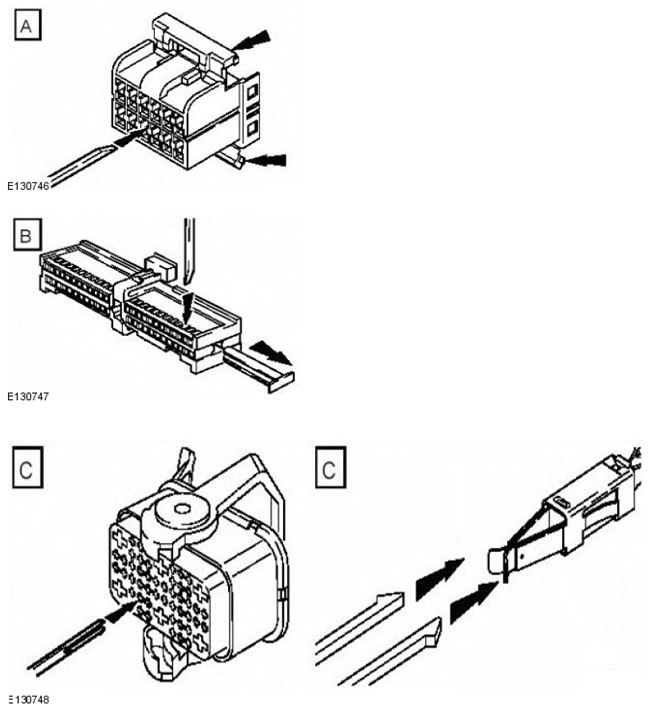
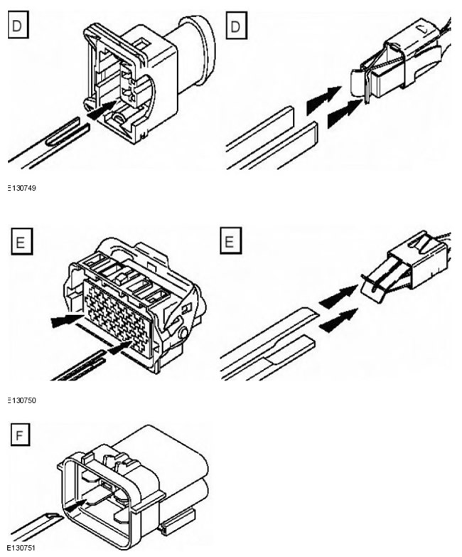
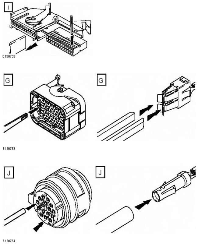
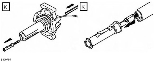
NOTE: The diagram shows electrical connector types, pins/sockets, pin extraction lug, and retainer release lug.
| Type of contact in the electrical connector | Pin or socket | Extraction tip | Tip for detaching the retainer |
| Mulitlock 040 Series | D | A | |
| Mulitlock 040 Series | B | A | |
| Mulitlock 070 Series | B | B | |
| Mulitlock 040 Series | D | B | |
| Series Econoseal III 070 | D | B | |
| Series Econoseal III 070 | B | B | |
| Series Econoseal III 070 | B | B | |
| Econoseal III J2 | D | B | |
| Econoseal III 250 series | B | F | |
| Econoseal III 250 series | D | B | |
| Econoseal III 250 series | B | F | |
| Econoseal III 250 series | D | B | |
| Microtimer II 1.5 mm | D | C | |
| Microtimer II 1.5 mm | B | C | |
| Standard Power Timer 4.8 flat | D | G | |
| Standard Power Timer 5.8 Flat | B | D | |
| Standard Power Timer 5.8 Flat | B | D | |
| Standard Power Timer 2.8 flat | D | D | |
| Standard Power Timer 4.8 flat | D | G | |
| Standard Power Timer 5.8 Flat | B | D | |
| Ford 2.8 flat | D | E | H |
| Mulitlock 070 Series | D | B | |
| Mulitlock 070 Series | B | B | |
| Junior power timer 2.8 flat | D | D | |
| Sumitomo TS90 connector | B | B | H |
| Modu IV gold plated | D | B | |
| Mulitlock series 040 gold plated | D | A | |
| Micro qualock | D | I | |
| EECV | D | B | |
| EECV | D | B | |
| Kostal series diam. 1.50 | D | J | |
| AMP 6.3 flat | D | B | |
| Junior power timer 2.8 flat | D | D | |
| Series 2.8 | D | B | I |
| Sumitomo TS90 connector | D | B | H |
| Ducon 0.60 gold plated | D | K | |
| AMP 6.3 flat | D | D | |
| Econoseal III 250 series | B | F |
Repair procedure
Caveats:
- Do not use crimping pliers, wire strippers, butt connectors, heat shrink sleeves, or terminated wire harnesses not included in the Jaguar Harness Repair Kit. Each part is for use with other parts in the harness repair kit only.
- If the repair procedure calls for the use of an adhesive heat shrink sleeve, heat the sleeve to the melting point of the adhesive to ensure the seal is tight. Do not overheat the adhesive heat shrink sleeve to avoid damage to the wire harness insulation.
Do not make more than five repair joints in the wiring harness for any electrical connector; if more than five faults are found in one electrical connector, a new wiring harness must be installed.
Using an extractor and a correct tip, remove the bad pin from the electrical connector. Make sure the retainer is released before removing the contact.
CAUTION: Some contacts in the electrical connectors are gold-plated or gold-plated. In the event of failure, they should be replaced with a gold-plated wire harness terminated from the wire harness repair kit. It is difficult to determine the presence of gold plating in the socket, but the pins of the plug are easier to visually determine, so be sure to check the contacts of both the socket and the plug for the presence of gold plating. In no case should you mix gold-plated and tin-plated contacts, this will lead to premature failure of the electrical connector.
NOTE: Do not use wire that is smaller than the original diameter in the harness. Select the correct size and type of Terminated Wire Harness and Butt Connector from the Wire Harness Repair Kit.
Using wire cutters on a wire stripping tool, cut the terminated wire harness and harness cable to the required length.
NOTE: See illustration: Insulation stripping.
In the comparison table, find the correct length of insulation cut on the terminated wire harness, and set the desired length on the adjustable stop. Clamp the terminated wire harness in a wire stripper and remove the insulation.
Slide the cable identification sleeves onto the wire harness so that the base color of the cable is at the terminal.
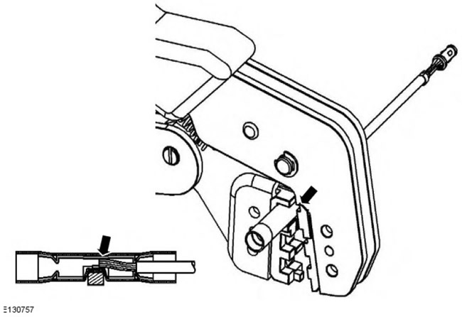
In the next step, do not overtighten. Place the selected butt connector in the crimping tool, ensuring that the holes and colors of the butt connector match. Ensure that the recess on the butt connector is positioned over the bottom clamp guide. Partially squeeze the handles so that the butt connector is securely locked in the hole. This will ensure that the butt connector does not move when the terminated wire harness is inserted into it.
NOTE: See illustration: Correct splice location.
Insert the terminated wire harness into the butt connector and make sure the wire is against the stopper. Squeeze the handles firmly, crimping the wire into the butt connector. When the handles are fully closed, the butt connector will release from the tool when they are released. If the handles are not fully closed, the clamps will hold the butt connector and it will not be possible to remove it from the tool until the wire is completely crimped (full closing of handles).
Make sure the harness cable is properly cut and the correct section of insulation is removed. If multiple splice points are required, butt connectors should not be crimped onto the wire harness at the same distance from the electrical connector. Splice points must be spaced apart to prevent multiple splice points from being located in the same area of the wire harness.
It is recommended to cover the splicing area with a heat shrink sleeve. This is not a requirement except for electrical connectors with seals. The small diameter sleeve is used for the red and blue terminated wire harnesses, and the large diameter sleeve is used for the yellow ones. It is recommended to place a heat shrink sleeve over the finished joint, however in some cases the sleeve does not pass over the contact. Check and, if necessary, install the correct size sleeve on the harness cable or terminated harness before crimping the splice to the harness.
Place the wire harness cable into the butt joint so that the hole is above the guide. Make sure the harness wire is pressed against the stop in the butt joint, then crimp the butt connector onto the harness.
Gently pull on the wire harness on either side of the splice to check if the splice is secure.
WARNING: Do not use open flames where fuel or oil has been spilled. Clean the area of oil and fuel residues and wait for the spilled fuel to evaporate.
Caveats:
- When using a heat source, make sure it is localized and will not damage surrounding materials.
- If the repair procedure calls for the use of an adhesive heat shrink sleeve, heat the sleeve to the melting point of the adhesive to ensure the seal is tight. Do not overheat the adhesive heat shrink sleeve to avoid damage to the wire harness insulation.
Using a suitable heat source, heat shrink the sleeve at the splice.
If additional terminated harnesses will be installed to the same electrical connector, make sure the wire is cut at a different distance from the previous splice. This will provide separation (if possible) splice points on the wiring harness and will prevent multiple splices in one place.
When splicing is complete, install the contacts into the electrical connector. Ensure the correct orientation of the contacts.
Install the wiring harness cover and secure with adhesive tape. Do not close the wiring harness all the way to the electrical connector, as the pins need to be slightly movable and not be firmly embedded in the connector or wiring harness. Make sure the identification sleeves are visible at the wiring harness electrical connector.
Stripping insulation
Correct splicing location
Comments on this article